
Single focus compound lens and mold

a compound lens and single-focus technology, applied in the field of single-focus compound lens and mold, can solve the problems of eye fatigue, eye fatigue, and eye fatigue, and achieve the effect of preventing eye fatigu

Inactive Publication Date: 2006-04-06
JOE HYUN SOO
View PDF21 Cites 2 Cited by
  • Summary
  • Abstract
  • Description
  • Claims
  • Application Information

AI Technical Summary

Benefits of technology

[0012] Accordingly, the present invention has been made to solve the above-described problems, and it is an object of the present invention to provide a single focus compound lens that is capable of clearly observing objects that are disposed at substantially different distances while a user does something at a relatively near distance like reading or working with a computer, such that the fatigue of the eyes is prevented.
[0013] It is another object of the present invention to provide a mold for manufacturing a single focus compound lens in large quantities.
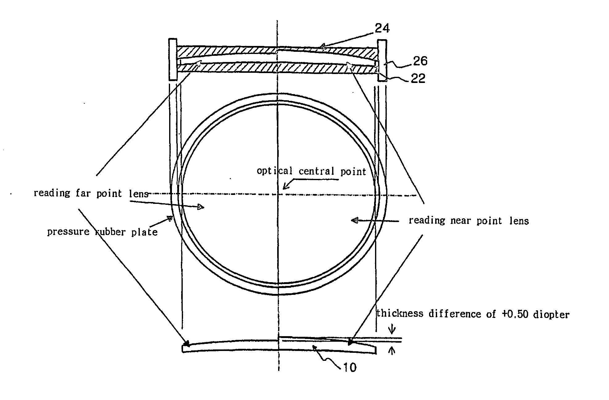
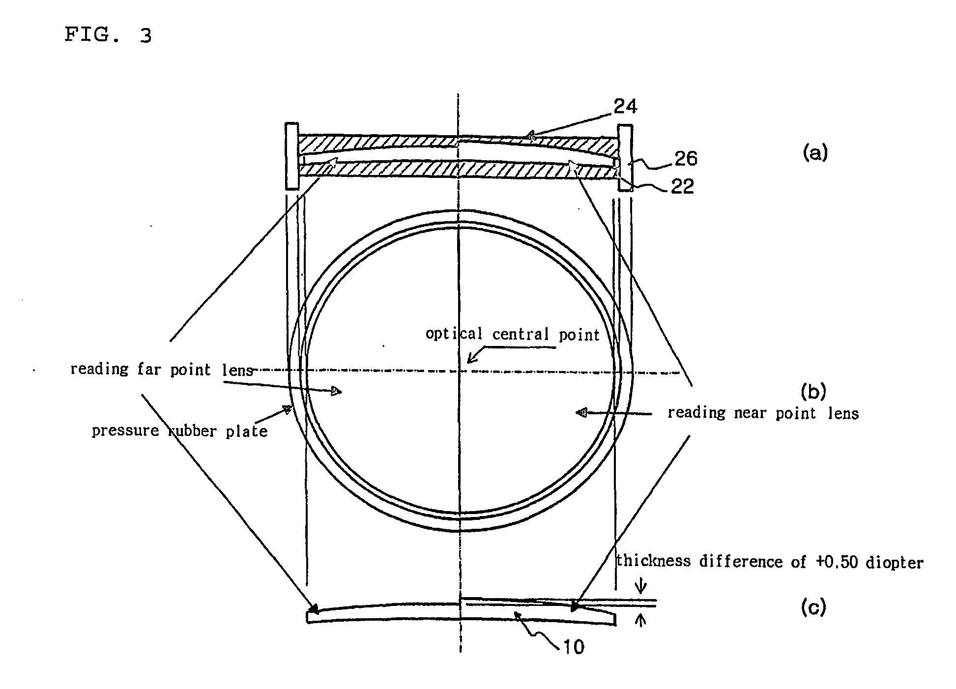
[0015] Preferably, the diopter difference between the reading far point diopter lens and the reading near point diopter lens is 0.5 diopter, and it compensates for a difference in curvature and thickness with respect to their focal points.

Problems solved by technology

This causes the manufacturing costs to become undesirably high.
At this time, if he or she is wearing generally reading glasses having a single diopter, he or she cannot view very well the monitor at a longer distance than the book, such that he or she feels his or her eyes get tired and also his or her posture becomes poor.
In case of the conventional multiple focal lens from the viewpoint of applying the need for the improvement, however, it has provided the following problem:

Method used


Image

  • Single focus compound lens and mold
  • Single focus compound lens and mold
  • Single focus compound lens and mold

Examples


Embodiment Construction

[0024] Now, an explanation of the preferred embodiment of the present invention will be given.

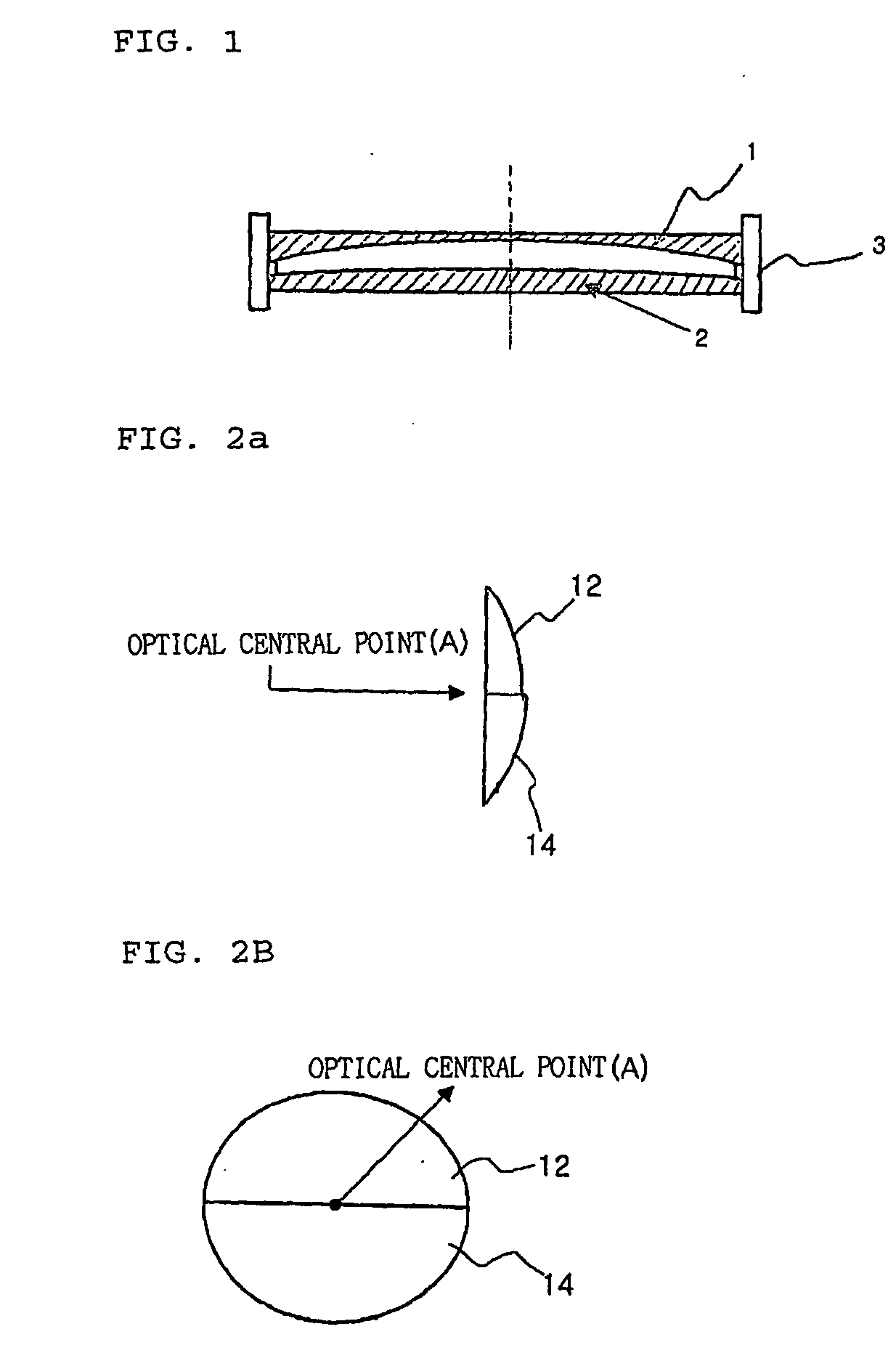
[0025]FIG. 2a is a side view of a single focus compound lens according to the present invention, and FIG. 2b is a front view of the single focus compound lens.

[0026] As shown in FIGS. 2a and 2b, the single focus compound lens according to the present invention has a diopter difference by making the upper and lower portions thereof different in their curvature and thickness with respect to a single optical central point A, wherein the upper portion becomes a reading far point diopter lens 12 and the lower portion becomes a reading near point diopter lens 14, their focuses corresponding to the single optical central point A.

[0027] Preferably, the diopter difference between the reading far point diopter lens 12 and the reading near point diopter lens 14 is 0.5 diopter, as shown in Table 1.

TABLE 1Reading near point dioptersReading far point diopters1.000.501.250.751.501.001.751.252.001.502...


PUM

PropertyMeasurementUnit
heightaaaaaaaaaa
lengthaaaaaaaaaa
distanceaaaaaaaaaa

Abstract

Disclosed is a single focus compound lens and a mold for manufacturing the single focus compound lens, where the single focus compound lens has a reading far point diopter lens and a reading near point diopter having different diopters that are integrally molded to have the same optical central point and the mold has the two divided areas with respect to the optical central point, each of the two areas forming an inner peripheral surface having a difference in curvature and thickness corresponding to the diopter difference, such that near distance works like reading or doing with a computer can be accomplished without any trouble and the fatigue of eyes caused due to the failure of correspondence of focuses can be prevented.

Description

TECHNICAL FIELD [0001] The present invention relates to a single focus compound lens and a mold for manufacturing the same, and more particularly, to a single focus compound lens that makes the focal point of the area for viewing a relatively longer distance and the focal point of the area for viewing a relatively shorter distance at a short distance correspond to each other, such that the fatigue of eyes caused when the focal points differ can be prevented, and to a mold for manufacturing a single focus compound lens. BACKGROUND ART [0002] As well known, a glass lens has been used for curing people of various types of abnormal visual acuities like hyperopia, myopia, presbyopia, and so on which are generally caused by the troubles with the lens of an eyeball. In some cases, especially, there is a need for the lens having one or more diopters, and to satisfy the need, is provided multiple focal lens like double focal lens. [0003] For example, as people get older, they suffer from bot...

Claims


Application Information

Patent Timeline
Patent Type & Authority Applications(United States)
IPC IPC(8): B29D11/00A01J21/00G02C7/04G02C7/02G02C7/06
CPCB29D11/00028G02C7/06G02C7/02B29D11/00528G02C7/04
Inventor JOE, HYUN-SOO
Owner JOE HYUN SOO
Learn More