Eureka AIR delivers breakthrough ideas for toughest innovation challenges, trusted by R&D personnel around the world.

Apparatus and method for virtual prototyping of blow molded objects

a technology of blow molding and apparatus, applied in the field of virtual prototyping of blow molding objects, can solve the problems of high cost of trial and error process, high cost of actual prototype production, and other software design tools failing to take into accoun

Inactive Publication Date: 2006-04-06
PLASTIC TECH INC
View PDF9 Cites 10 Cited by
  • Summary
  • Abstract
  • Description
  • Claims
  • Application Information

AI Technical Summary

Benefits of technology

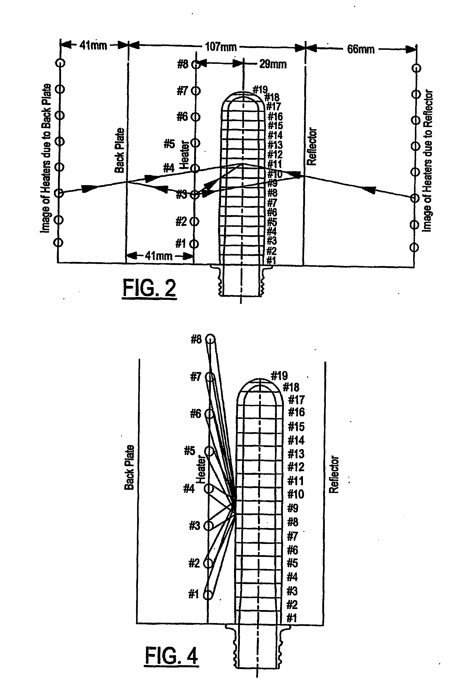
[0009] The present invention has the advantage of simulating a heating of a plastic preform to determine one or more cross sectional thermal profiles of a final heated preform for modeling or virtually prototyping plastic containers.

Problems solved by technology

Issues concerning blow-molding operations involve the expansion of the material to the final desired shape.
Expansion factors such as undesired thinning of certain areas of the article of manufacture leads to further re-tooling of the mold in those critical areas to reduce the effects of the unwanted expansion and thinning.
This trial and error process becomes costly as new mold and / or performs need to be designed and created.
Furthermore, run times for producing prototypes of the actual article are typically costly.
However, these and other software design tools fail to take into consideration a combination of factors such as temperature affects of all heating and cooling sources upon the entire preform, the stress / strain behavior of the material throughout the molding process, and the energy incident to the preform during the entire molding process.

Method used


Image

  • Apparatus and method for virtual prototyping of blow molded objects
  • Apparatus and method for virtual prototyping of blow molded objects
  • Apparatus and method for virtual prototyping of blow molded objects

Examples


Embodiment Construction

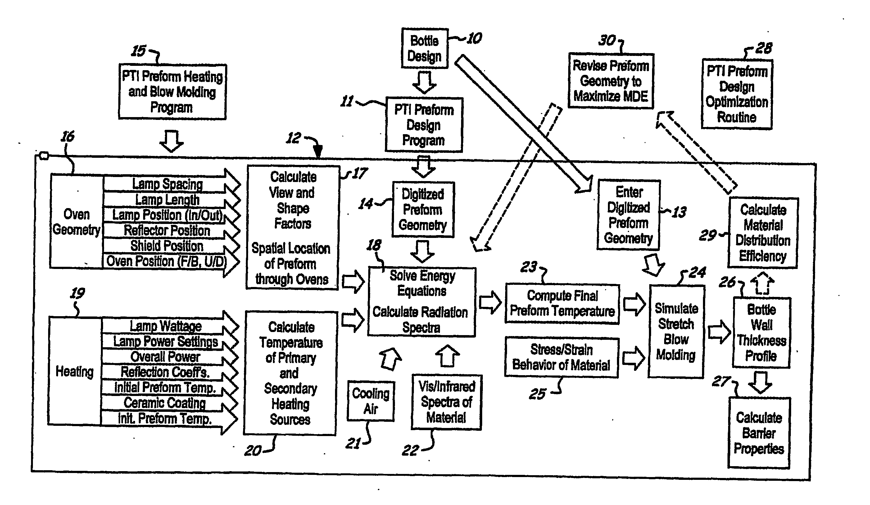
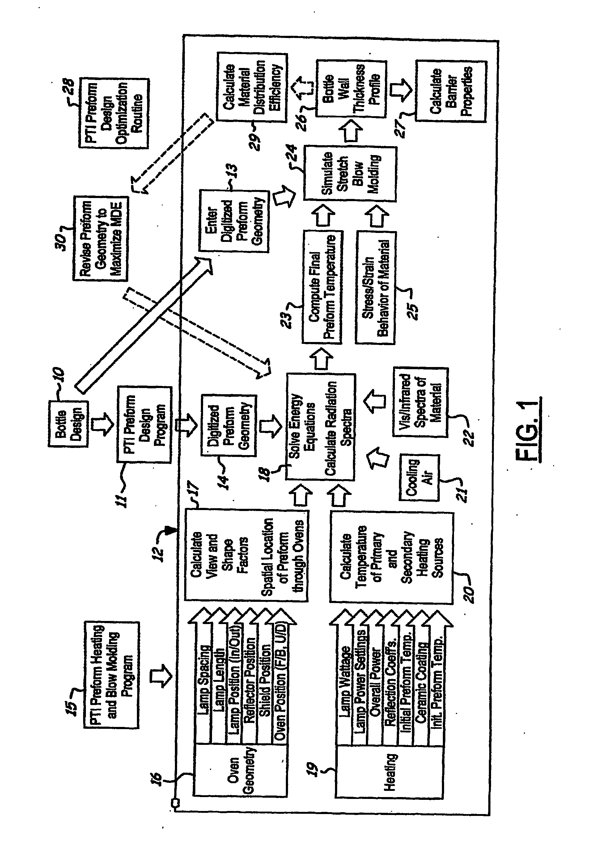
[0021] There is shown in FIG. 1 a flow diagram of the method of virtual prototyping of plastic containers in accordance with the present invention. The method can be implemented in software run on a computer. In a first step 10, a container (e.g., bottle) design is created by any known process thereby generating bottle geometry data. This data is entered in digitized form into a Preform Design Program 11 to generate digitized preform geometry. Inputs to the program 11 are the bottle geometry, the container and finish weight and the resin stretching characteristic. Preform designs are created so the designs may be stripped off of a core (i.e., error checking for undercuts) and positions of transition regions of the preform may be adjusted so that shoulder regions of the preform coincides with that of the bottle, if desired. A virtual prototyping module 12 receives the digitized bottle geometry in a step 13 and the digitized preform geometry in a step 14. A Preform Heating and Blow Mo...


PUM

PropertyMeasurementUnit
Temperatureaaaaaaaaaa
Thicknessaaaaaaaaaa
Volumeaaaaaaaaaa

Abstract

A method is provided for simulating the heating of a plastic preform. A preform geometry is input into a preform design program. Oven geometry and spatial location of the preform throughout at least one oven is provided. Heating information is provided and the temperatures of the primary and secondary sources are calculated. Energy equations are solved based upon the preform geometry, the spatial location of the preform, the temperature the cooling air, and the absorption spectra of the preform material. At least one cross sectional thermal profile of a final heated preform is computed.

Description

CROSS REFERENCE TO RELATED APPLICATIONS [0001] This application claims the benefit of U.S. provisional patent application Ser. No. 60 / 441,419 filed Jan. 21, 20031.STATEMENT REGARDING FEDERALLY SPONSORED RESEARCH [0002] Not Applicable. BACKGROUND OF THE INVENTION [0003] 1. Field of the Invention [0004] The present invention relates generally to the design of blow molded objects and, in particular, to an apparatus and method for simulating the heating of a plastic preform. [0005] 2. Description of the Related Art [0006] Blow-molding operations typically involve encapsulating a heated plastic material such as a preform within the interior of a mold, applying a pressure to the interior of the preform so as to expand the preform against the mold cavity to form an article of manufacture. Issues concerning blow-molding operations involve the expansion of the material to the final desired shape. Expansion factors such as undesired thinning of certain areas of the article of manufacture lead...

Claims


Application Information

Patent Timeline
IPC IPC(8): G06G7/48B29C33/38B29C35/00B29C49/00B29C49/06B29C49/64B29C49/78G06F17/50
CPCB29C33/3835B29C35/002B29C49/00B29C49/06B29C49/12B29C49/42B29C49/64B29C49/78B29K2105/253B29K2105/258B29L2031/7158G06F17/5018G06F2217/41G06F2217/80G06F2113/22G06F2119/08G06F30/23B29C49/424B29C49/42402B29C2949/0715B29C49/42398
Inventor CHANG, LONG FEIMUKHERJEE, SUMITSEMERSKY, FRANKE
Owner PLASTIC TECH INC
Why Eureka
Eureka Blog
Learn More