
Numerical simulation method for the flight-icing of helicopter rotary-wings

a numerical simulation and helicopter technology, applied in the field of numerical simulation of helicopter rotary-wing flight icing, can solve the problems of increasing the wing load and output torque, deteriorating the stall characteristics, and affecting the performance of flight icing

Inactive Publication Date: 2014-09-11
XIAN VIRTUAL DYNAMICS SIMULATION TECH
View PDF4 Cites 14 Cited by
  • Summary
  • Abstract
  • Description
  • Claims
  • Application Information

AI Technical Summary

Benefits of technology

The patent describes a method for accurately capturing the vortex structure and calculating the shape of ice. This is done by separately building and solving the governing equations for the air and the snow-water mixture flows, taking into account the interaction between the two phases. This method is reliable, efficient, and practical.

Problems solved by technology

For all type aircrafts, the flight-icing has a performance degradation and severely to a damage.
First, the ice increases the wing loads and output torques of helicopter, and makes aircraft configuration changing, which could deteriorates the stall characteristics.
The shedding of the ice on the rotary-wings makes the wing loads uneven, which induces more serious vibration and noise.
All above problems make the anti-and de-icing to the rotary-wings be the core and the most complicated task for the helicopter safety flight.
Compared to the fixed-wing aircrafts, the rotary-wing aircrafts behave more complicated aerodynamic characteristics, such as the interference between the two adjacent wings, the centrifugal forces produced by wing rotation, etc.
The natural flight test has seasonal limitations and is risky in some extreme situations.
Moreover, the generation of the size distribution of SWD like in the atmosphere in the icing wind tunnel is not possible.
It is more difficult to capture the contact discontinuity interfaces in numerical simulation, since very little amount of numerical diffusion embodied in numerical method could make them smeared to a point damaging the simulation accuracy.

Method used


Image

  • Numerical simulation method for the flight-icing of helicopter rotary-wings
  • Numerical simulation method for the flight-icing of helicopter rotary-wings
  • Numerical simulation method for the flight-icing of helicopter rotary-wings

Examples


Embodiment Construction

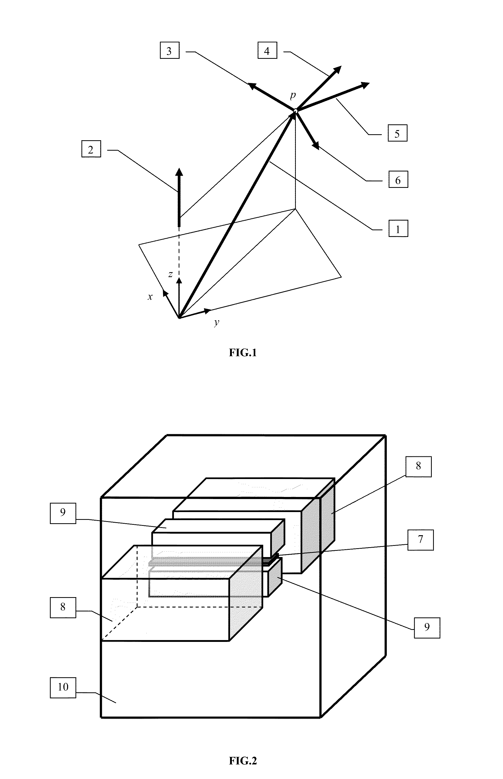
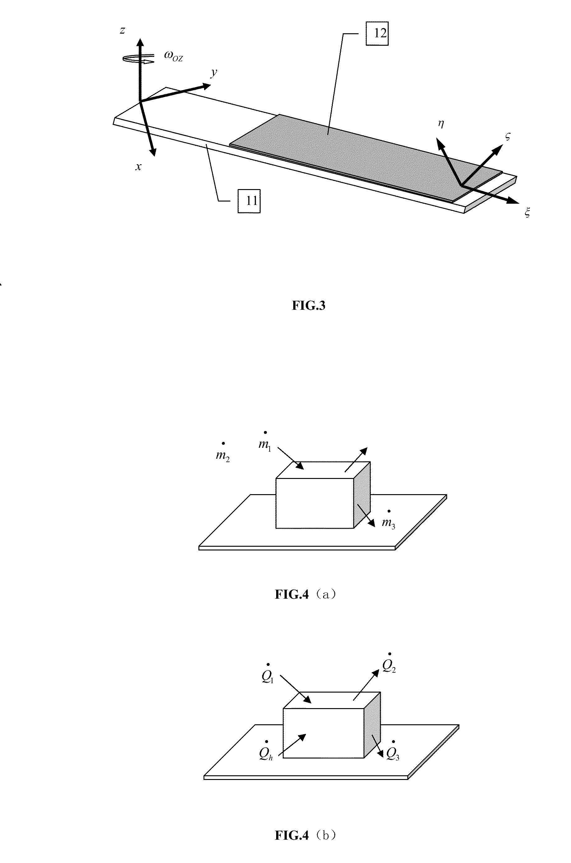
[0089]A preferred embodiment according to the invention is illustrated following. It is related to a numerical simulation method for the flight-icing of helicopter rotary-wings with a section view of NACA0012 airfoil. This method can be embodied using the computer language codes and the codes can be run on computers to do the simulation.

[0090]The computational domain only covers one quarter quadrant, where includes one rotary-wing, with spanwise ratio of 7 and two-dimensional section view of NACA0012 airfoil, rotating around Z-axial. The computing grid is a multi-block structured hexahedron grid. On each two-dimensional section view, the grid is the 0-type grid with 192 cells around the airfoil and 48 cells along normal direction of airfoil wall. Totally 32 cells are along the spanwise of the wing. The FIG. 6 shows the computing grid on the surface of one three-dimensional wing with NACA0012 section view. The spatial discretization scheme in the numerical method to solve any governi...


PUM


Abstract

The present invention is related to a numerical simulation method for the flight-icing of helicopter rotary-wings. This invention includes the algorithm of adding the voracity compensation force term to the momentum and energy equations describing the air-supercooled water droplets two-phase rotational flows in the single fluid two-phase flow system in wake domain of helicopter-rotary wings; the algorithm of adding the centrifugal and Coriolis force to the slip velocity equation; the models describing the water film and icing progress containing the effect of the centrifugal and Coriolis force; and the procedure using the above algorithms and models to do simulation.

Description

TECHNICAL FIELD OF THE INVENTION[0001]The present invention is related to the application of computational fluid dynamics on the aerospace engineering. Particularly, it is a numerical method for simulating the flight-icing of helicopter rotary-wings. This method can be embodied using the computer codes and the code can be run on computers to simulate the flight-icing of helicopter rotary-wings.BACKGROUND OF THE INVENTION[0002]Helicopter had widely been used in civil and military domains owing to its flexibility. Generally, the flight attitude of helicopter is below 6000 meter, within which the supercooled water droplets (SWD) in the atmosphere, which exist in form of water droplets at a temperature below the dew point, will impinge on aircraft surfaces, such as wing, body, cockpit, tail, engine nacelle, etc., which results in water film (WF) on aircraft surfaces. If the liquid water contain (LWC, the mass of the SWD per unit volume, with dimension kg / m3) is too high, the accreted wa...

Claims


Application Information

Patent Timeline
Patent Type & Authority Applications(United States)
IPC IPC(8): G06F17/50
CPCG06F17/5009G06F30/15G06F30/20G06F2111/10
Inventor LU, MING
Owner XIAN VIRTUAL DYNAMICS SIMULATION TECH
Learn More