Apparatus and method for measuring two- or three-phase fluid flow utilizing one or more momentum flow meters and a volumetric flow meter

a technology of momentum flow meter and volumetric flow meter, which is applied in the direction of volume/mass flow measurement, measurement device, instrument, etc., can solve the problems of high accuracy, high cost of pumping energy, and gas separation device, and achieve high flow rate measurement accuracy and low cost

Inactive Publication Date: 2000-03-07
AGAR CORP
View PDF13 Cites 14 Cited by
  • Summary
  • Abstract
  • Description
  • Claims
  • Application Information

AI Technical Summary

Benefits of technology

Accordingly, one object of the invention is to provide a new and improved apparatus and method for measuring multiphase flow by means of simple, low cost, compact equipment which has high flow rate measuring accuracy.

Problems solved by technology

This method can yield high accuracy, but require gas-separating devices which are either very large or are very sensitive to flow rates and the liquid's viscosity, surface tension, etc.
This requires a large pressure drop, which is costly in terms of pumping energy.
While information has been compiled on the pressure drops of a two-phase fluid comprising of water and air, it has not been possible to predict the pressure drops for other, more unique multi-phase fluids.

Method used


Image

  • Apparatus and method for measuring two- or three-phase fluid flow utilizing one or more momentum flow meters and a volumetric flow meter
  • Apparatus and method for measuring two- or three-phase fluid flow utilizing one or more momentum flow meters and a volumetric flow meter
  • Apparatus and method for measuring two- or three-phase fluid flow utilizing one or more momentum flow meters and a volumetric flow meter

Examples


Embodiment Construction

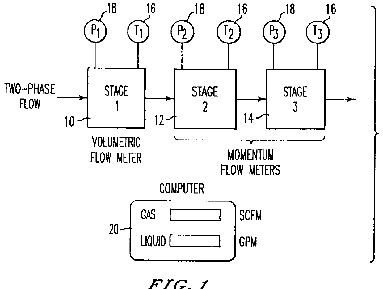
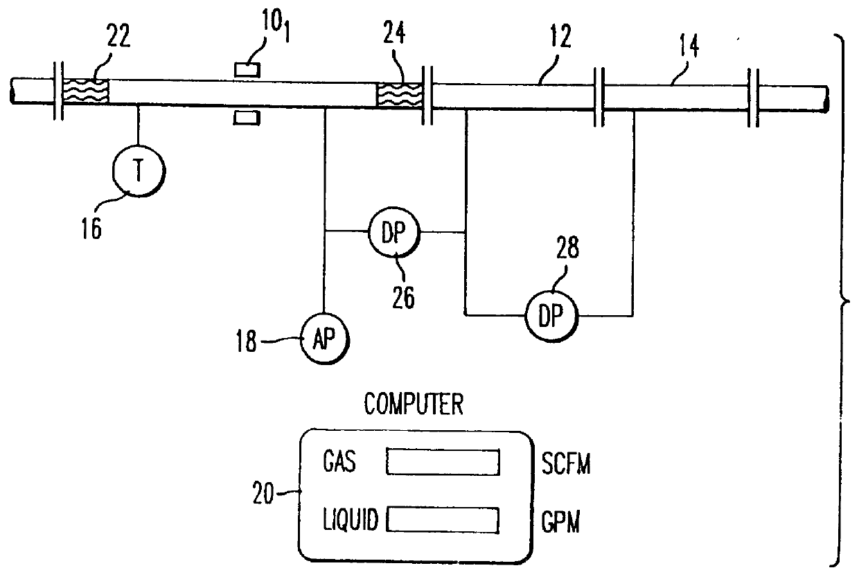
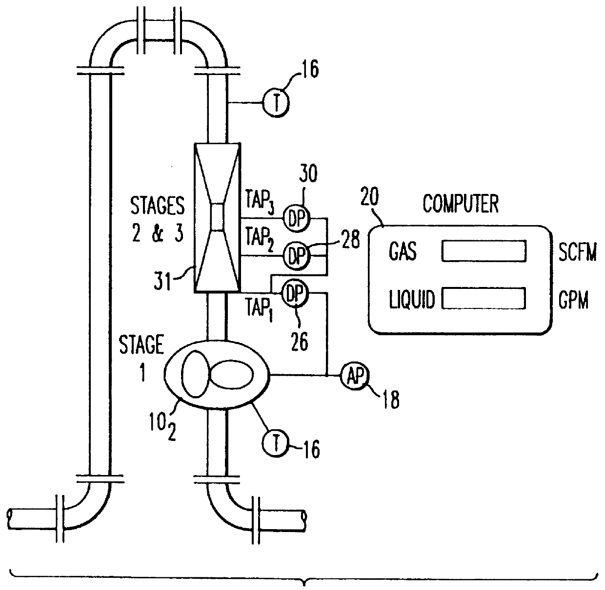
Referring now to the drawings, wherein like reference numerals designate identical or corresponding parts throughout the several views, and more particularly to FIG. 1 thereof, there is shown schematically an embodiment of the apparatus of the invention, including a volumetric flowmeter 10 serving as a first stage in which a mixture of gas and liquid flows through the volumetric flow meter 10. This flow meter 10 measures the total flow rate for the mixture. The mixture then flows through second and third stages, consisting of two momentum flow meters 12 and 14 with different dimensions (for example, two venturi flow meters with different throat diameters). Momentum flow meters are flow meters that measure the momentum flux of the fluid (M=mv). In order to avoid using a void fraction meter, the present invention forces the velocity ratio between the gas and the liquid (slip ratio) inside the apparatus to be a known value, a slip ratio of one being conveniently enforced. This is achie...


PUM


Abstract

An apparatus and method for measuring the flow rates of each component of two-phase flow consisting of a gas and a liquid or three-phase flow consisting of water, oil and gas, including a first volumetric flow meter stage, and second and third momentum flow meter stages coupled in a series flow path with the volumetric flow meter stage and in which a velocity ratio between the gas and the liquid in the series flow path is maintained to be one. A processor calculates flow rates of the components of flow by solving volumetric flow and momentum or energy equations defining flow through the first through third stages utilizing a volumetric flow output from the first stage and momentum flux outputs from said second and third stages, and an indicator displays flow of liquid and gas or oil, water and gas components of the flow. To measure three-phase flow, a water-cut meter is provided to determine the amount of water flow, which is then used by the processor to determine the flow of the rest of the liquid. The second and third momentum flow meter stages can be implemented by two separate momentum flow meters or by a single momentum flow meter, such as a venturi flow meter having a venturi nozzle including pressure taps for obtaining at least two differential pressure measurements. In the event that the density of the liquid component is known, a single momentum flow meter stage is sufficient.

Description

BACKGROUND OF THE INVENTION1. Field of the InventionThis invention relates to-an apparatus and method for measuring two-phase flow (liquid / gas) or three-phase flow (liquid / liquid / gas) of fluids.2. Discussion of BackgroundThe measurement of oil, water and gas flow finds application in various fields. In oil production, it is required for reservoir control and fiscal reasons. High accuracy of measurement is necessary as well as small instrumentation space requirements. Additional applications exist in petrochemical, nuclear and other industries.In the past, three principal methods have been utilized for flow measurements.As disclosed in U.S. Pat. No. 4,760,742, the gas in a liquid is physically separated from the liquid, and each fluid is measured separately. A water-cut monitor is used to measure the amount of the water and the oil in the liquid phase. Two conventional single-phase flow meters are used to measure the gas and the liquid flow rates. This method can yield high accuracy,...

Claims


Application Information

Patent Timeline
Patent Type & Authority Patents(United States)
IPC IPC(8): G01F1/34G01F1/74G01F1/36
CPCG01F1/36G01F1/74
Inventor AGAR, JORAMFARCHI, DAVID
Owner AGAR CORP
Why Eureka
Try Eureka