
Apparatus and method for formation evaluation

a technology of formation evaluation and apparatus, applied in the field of subsurface formation evaluation techniques, can solve the problems of false results, erroneous and/or unusable results, and high cost of wellbore operations

Inactive Publication Date: 2006-04-13
SCHLUMBERGER TECH CORP
View PDF41 Cites 87 Cited by
  • Summary
  • Abstract
  • Description
  • Claims
  • Application Information

AI Technical Summary

Benefits of technology

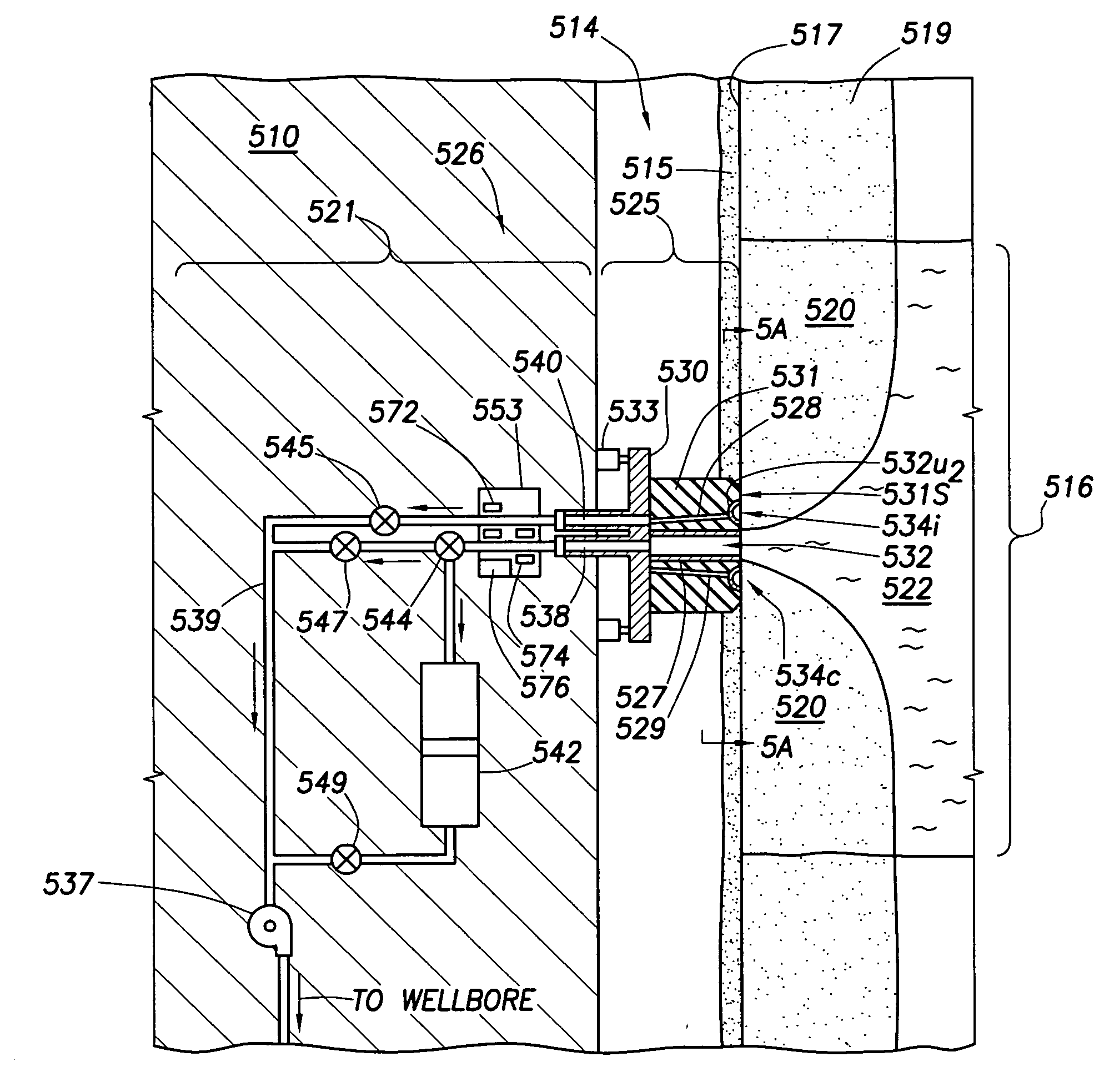
[0037] In a particular embodiment, the inventive apparatus further includes a flow line extending through a portion of the downhole tool and fluidly communicating with the first and second inlets of the probe assembly for admitting one of virgin fluid, contaminated fluid and combinations thereof into the downhole tool. One or more pumps are carried within the downhole tool for drawing one of virgin fluid, contaminated fluid and combinations thereof into the downhole tool via the flow line. It is further preferred that a sample chamber be carried within the downhole tool for receiving one of virgin fluid, contaminated fluid and combinations thereof from the pump(s), as well as an instrument for analyzing fluid drawn into the downhole tool via the flow line and the pump(s). The downhole tool may be adapted for conveyance within a wellbore via a wireline, a drill string, or on coiled tubing.
[0038] In a still further aspect, the present invention provides a packer for employment by a probe assembly carried on downhole tool conveyed in a wellbore penetrating a subsurface formation surrounded by a layer of contaminated fluid, the subsurface formation having a virgin fluid therein beyond the layer of contaminated fluid. The packer includes an elastomeric packer body having a distal surface adapted for sealingly engaging a portion of the wellbore. The packer body has an outer diameter and an inner diameter, the inner diameter being defined by a bore through the packer body. The packer body is further equipped with one or more channels formed in the distal surface and arranged in an annular cleanup intake intermediate the inner and outer diameters. A plurality of braces is disposed in the one or more channels of the packer body and are operatively connected to define a flexible bracing ring. At least one passageway extends through the packer body for conducting one of virgin fluid, contaminated fluid and combinations thereof through the packer body.

Problems solved by technology

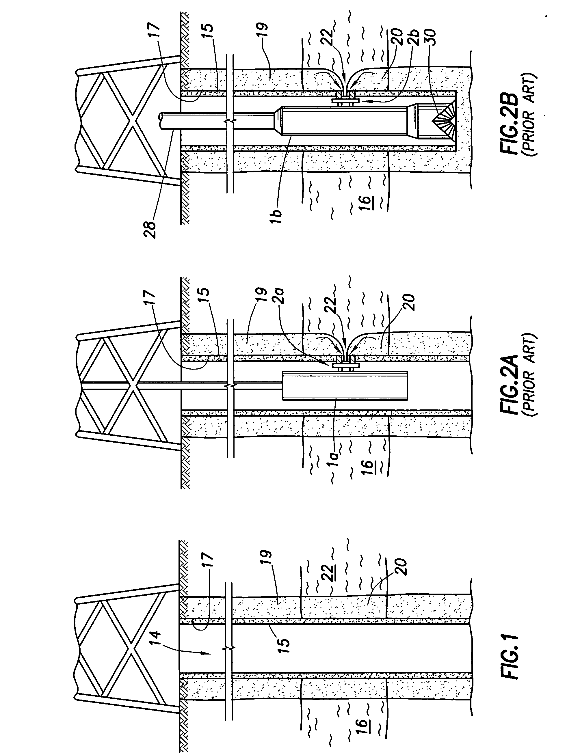
However, it has been discovered that when the formation fluid passes into the downhole tool, various contaminants, such as wellbore fluids and / or drilling mud may, and often do, enter the tool with the formation fluids.
Moreover, contamination may cause costly delays in the wellbore operations by requiring additional time for more testing and / or sampling.
Additionally, such problems may yield false results that are erroneous and / or unusable.
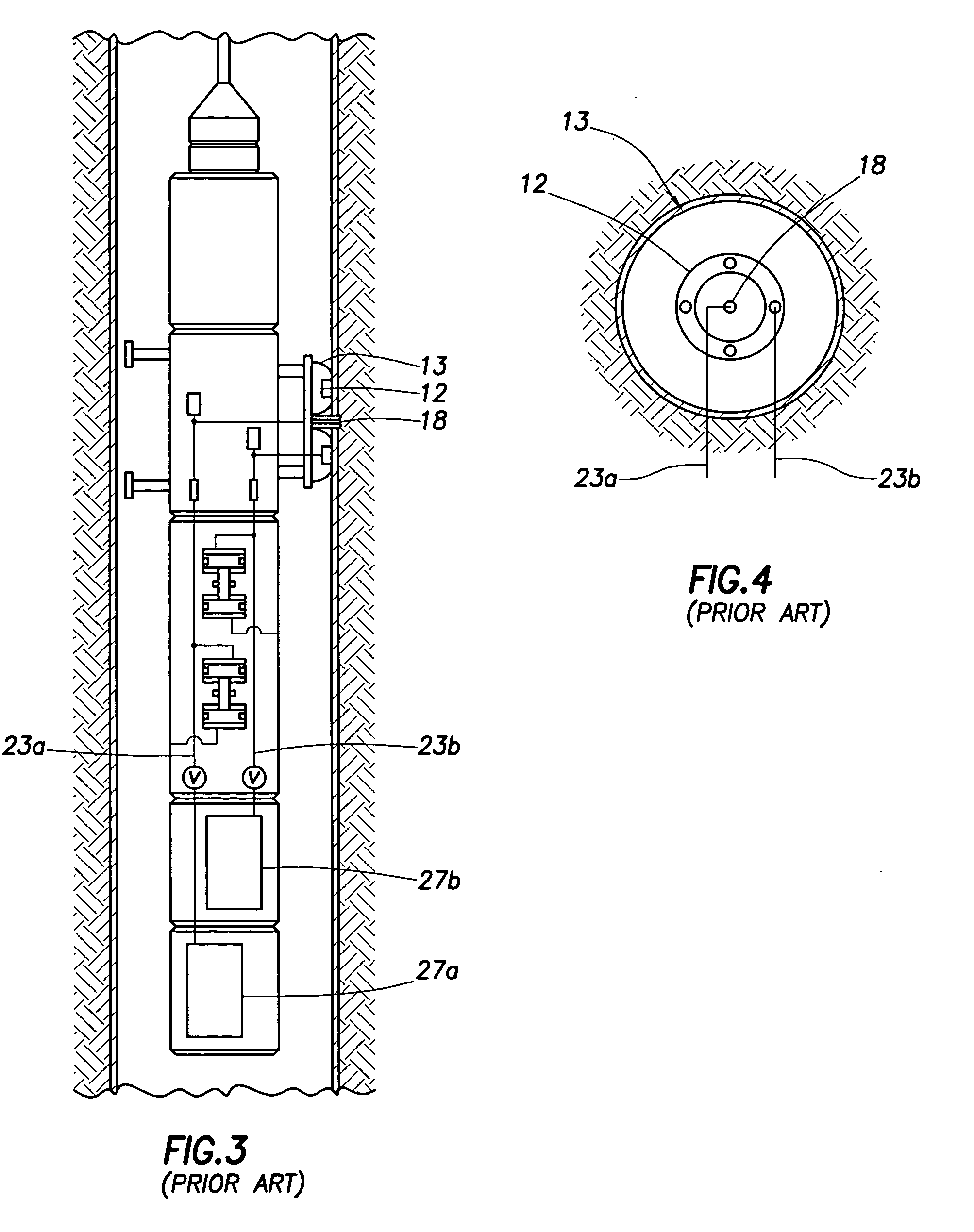
In some cases, cross-flow between adjacent flowlines may cause contamination therebetween.

Method used


Image

  • Apparatus and method for formation evaluation
  • Apparatus and method for formation evaluation
  • Apparatus and method for formation evaluation

Examples


Embodiment Construction

[0058] Presently preferred embodiments of the invention are shown in the above-identified figures and described in detail below. In describing the preferred embodiments, like or identical reference numerals are used to identify common or similar elements. The figures are not necessarily to scale and certain features and certain views of the figures may be shown exaggerated in scale or in schematic in the interest of clarity and conciseness.

[0059] Referring now to FIG. 5, a fluid sampling system 526 of a downhole tool 510 is shown to include a probe assembly 525 and a flow section 521 for selectively drawing formation fluid into the desired portion of the downhole tool. The downhole tool 510 is conveyed in a wellbore 514 surrounded by an invaded zone 519 containing a layer of contaminated fluid 520. The wellbore 514 penetrates a subsurface formation 516 having a virgin fluid 522 therein beyond the layer of contaminated fluid 520.

[0060] The probe assembly 525 includes a probe body 5...


PUM


Abstract

A probe assembly samples fluid from a wellbore penetrating a subsurface formation having a virgin fluid therein beyond a layer of contaminated fluid surrounding the wellbore. The probe assembly includes a probe body extendable from a downhole tool, and a packer carried by the probe body and having a distal surface adapted for sealingly engaging the wellbore. The packer has an outer and inner periphery, with the inner periphery being defined by a bore through the packer. The packer is further equipped with channel(s) formed in the distal surface and arranged to define an annular cleanup intake intermediate the inner and outer peripheries. The passageway(s) extend(s) through the packer for conducting virgin fluid and / or contaminated fluid between the channel(s). A sampling tube is sealingly disposed in the bore of the packer for conducting virgin fluid to a second inlet in the probe body and the downhole tool.

Description

BACKGROUND OF THE INVENTION [0001] 1. Field of the Invention [0002] The present invention relates to techniques for evaluating a subsurface formation using a probe assembly conveyed on a downhole tool positioned in a wellbore penetrating the subsurface formation. More particularly, the present invention relates to techniques for reducing the contamination of formation fluids drawn into and / or evaluated by the downhole tool via the probe assembly. [0003] 2. Background of the Related Art [0004] Wellbores are drilled to locate and produce hydrocarbons. A string of downhole pipes and tools with a drill bit at an end thereof, commonly known in the art as a drill string, is advanced into the ground to form a wellbore penetrating (or targeted to penetrate) a subsurface formation of interest. As the drill string is advanced, a drilling mud is pumped down through the drill string and out the drill bit to cool the drill bit and carry away cuttings and to control downhole pressure. The drillin...

Claims


Application Information

Patent Timeline
Patent Type & Authority Applications(United States)
IPC IPC(8): E21B49/08E21BE21B49/10
CPCE21B49/10
Inventor NOLD, RAYMOND V. IIIZAZOVSKY, ALEXANDER F.ERVIN, STEVEDEL CAMPO, CHRISTOPHER S.BRIQUET, STEPHANE
Owner SCHLUMBERGER TECH CORP
Learn More