Tape dispenser with configured side walls

Inactive Publication Date: 2006-04-13
DICKIE ROBERT G
View PDF8 Cites 5 Cited by
  • Summary
  • Abstract
  • Description
  • Claims
  • Application Information

AI Technical Summary

Benefits of technology

[0007] The tape dispenser of the present invention has first and second sides which each have an inner wall, an outer wall, an upper wall and a bottom wall. The first and second sides are connected to each other to form a chamber into which the roll of tape is received. A tape support extends between the inner walls of the first and second sides. When a roll of adhesive tape is received on the support, it is substantially concealed within the chamber. The upper wall and outer walls of the dispenser are provided with patterned ridges to assist the younger child to grip the dispenser. The dispenser has a rear section and a forward section. The forward section

Problems solved by technology

The dispensers of the prior art function well, but may be problematic when used by small children.
As they try to pull the free end of the tape over the cutter blade, their smaller fingers tend to interfere with the rotation of the roll of tape.
This can lead to frustration on their part causing them to grip the dispenser more tightly and to pull on the free end of the tape more vig

Method used


Image

  • Tape dispenser with configured side walls
  • Tape dispenser with configured side walls
  • Tape dispenser with configured side walls

Examples


Example

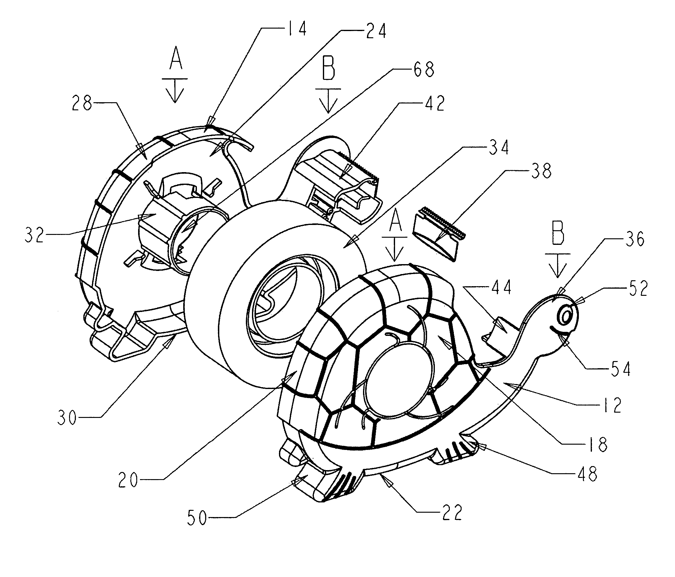
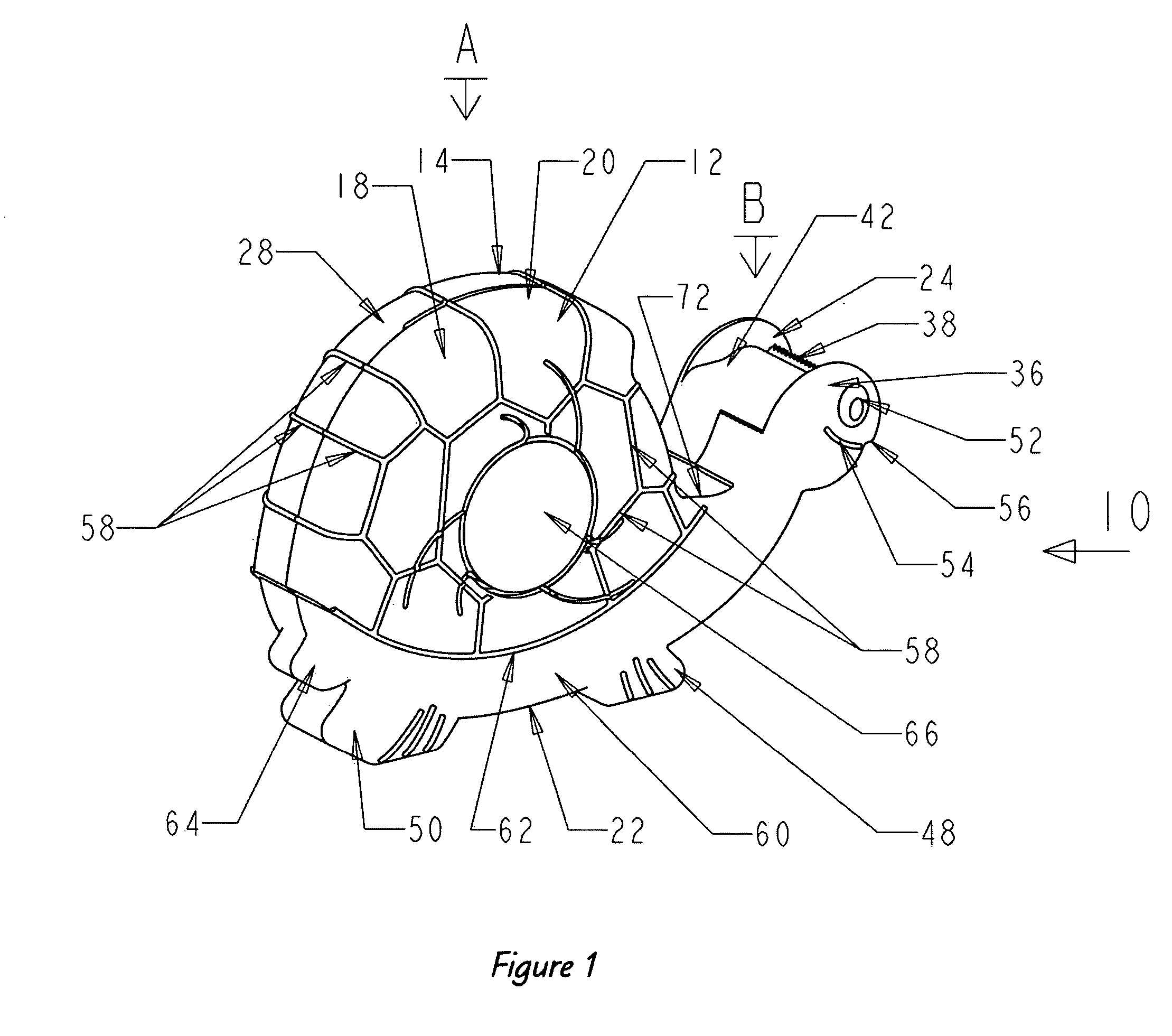
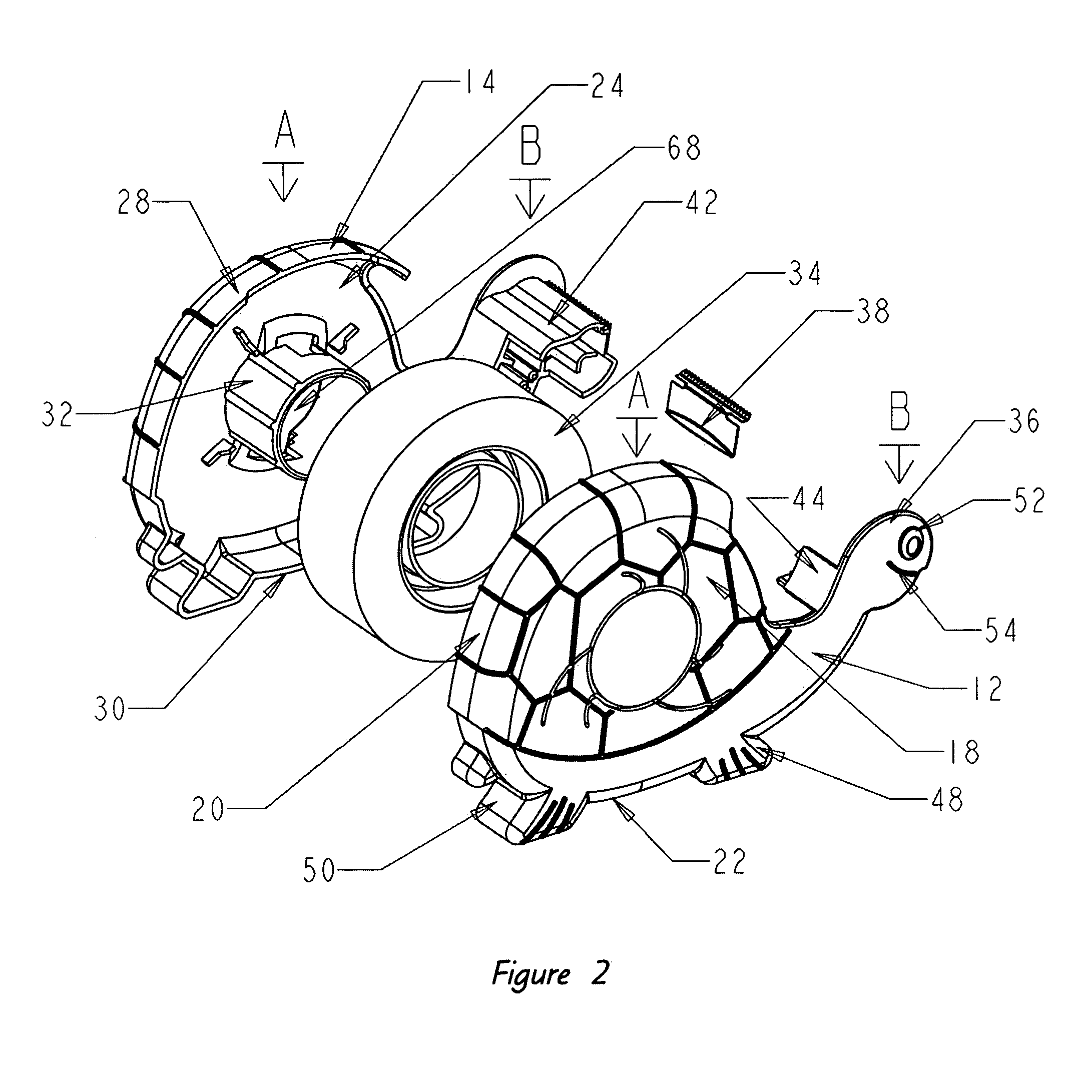
[0018] Referring to FIGS. 1-4A, there is shown a first embodiment of a tape dispenser in accordance with the present invention and generally indicated at 10. Dispenser 10 has a first side 12 and a second side 14 which are substantially identical in shape. First and second sides 12, 14 preferably are snap-fitted together but may alternatively be adhesively attached to each other or connected together in any other suitable manner. First side 12 includes an inner wall 16 (FIG. 4), an outer wall 18, an upper wall 20 and a bottom wall 22. Second side 14 includes an inner wall 24 (FIG. 2), an outer wall 26, an upper wall 28 and a bottom wall 30. First and second sides 12, 14, preferably are molded from a material such as polystyrene.

[0019] A tape support 32 (FIG. 2) extends from the inner wall 24 of second side 14 toward the inner wall 16 of first side 12. A roll of adhesive tape 34 is received on support 32. A cooperating tape support (not shown) may extend from inner wall 16 of first s...

Example

[0025] Referring to FIGS. 5-7A0, there is shown a second embodiment of tape dispenser in accordance with the present invention and generally indicated at 110. Dispenser 110 is shaped to represent a stylized snail and various features of the dispenser consequently differ from those of the first embodiment. First and second sides 112, 114 of dispenser 110 are formed with a rear section A and a forward section B. Forward section B of each of first and second sides 112, 114 includes an end portion 136 shaped as a snail's head and includes an eye 152 and a mount 154. An tab 174, representing an antenna, is formed rearwardly of eyes 152. Cutter blade 138 is mounted forward of tabs 174 and between end portions 136. Cutter blade 138 is mounted a spaced distance inwardly from outer edge 140. Rear section A is again substantially circular in shape and includes a plurality of ridges 158. Ridges 158 radiate outwardly from approximately the center of rear section A and are configured into a spir...


PUM


Abstract

A tape dispenser for young children. The dispenser includes first and second sides that are formed in the shape of an animal and more particularly in the shape of a turtle or snail. The first and second sides are connected together to form a chamber into which a roll of tape is inserted. Each of the first and second sides includes an end portion that is enlarged. A cutter blade is mounted between the enlarged end portions and is positioned a spaced distance inwardly from an outer edge of each end portion. The upper and outer walls of the dispenser include a plurality of ridges to aid in the gripping of the dispenser. The ridges are shaped and positioned to represent the shells of either a turtle or a snail.

Description

BACKGROUND OF THE INVENTION [0001] 1. Technical Field [0002] This invention relates generally to tape dispensers. More specifically, the invention relates to tape dispensers for young children. Particularly, the invention relates to a tape dispenser which has sidewalls configured for easy gripping and that includes a recessed blade and rounded upper walls for protecting small hands. [0003] 2. Background Information [0004] A wide variety of adhesive tape dispensers have been proposed in the prior art. Typically, these dispensers have a side wall, an upper wall and a bottom wall. A tape support extends outwardly from the inner surface of the side wall and the roll of adhesive tape is received on this support. A cutter blade projects outwardly from the inner wall proximate the front end of the dispenser and the tape is pulled over the cutter blade to cut small pieces of the same therefrom. [0005] The dispensers of the prior art function well, but may be problematic when used by small c...

Claims


Application Information

Patent Timeline
IPC IPC(8): B26F3/02
CPCB65H35/0026B65H35/0073B65H2407/40Y10T225/238
Inventor DICKIE, ROBERT G.
Owner DICKIE ROBERT G
Why Eureka
Try Eureka