Side-emitting optical coupling device

Active Publication Date: 2006-04-13
CREELED INC
View PDF17 Cites 186 Cited by
  • Summary
  • Abstract
  • Description
  • Claims
  • Application Information

AI Technical Summary

Problems solved by technology

This path is not desirable and limits the efficiency of side extracted light.
The

Method used


Image

  • Side-emitting optical coupling device
  • Side-emitting optical coupling device
  • Side-emitting optical coupling device

Examples


Embodiment Construction

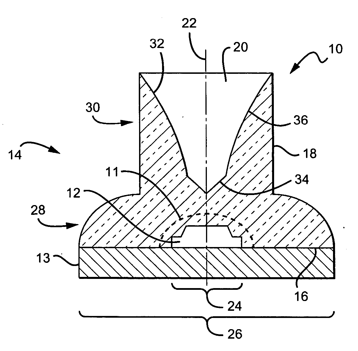
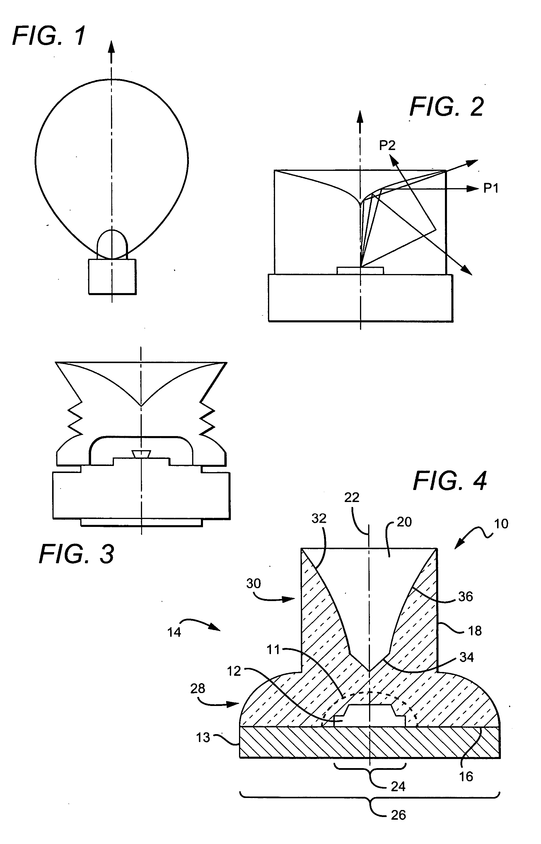
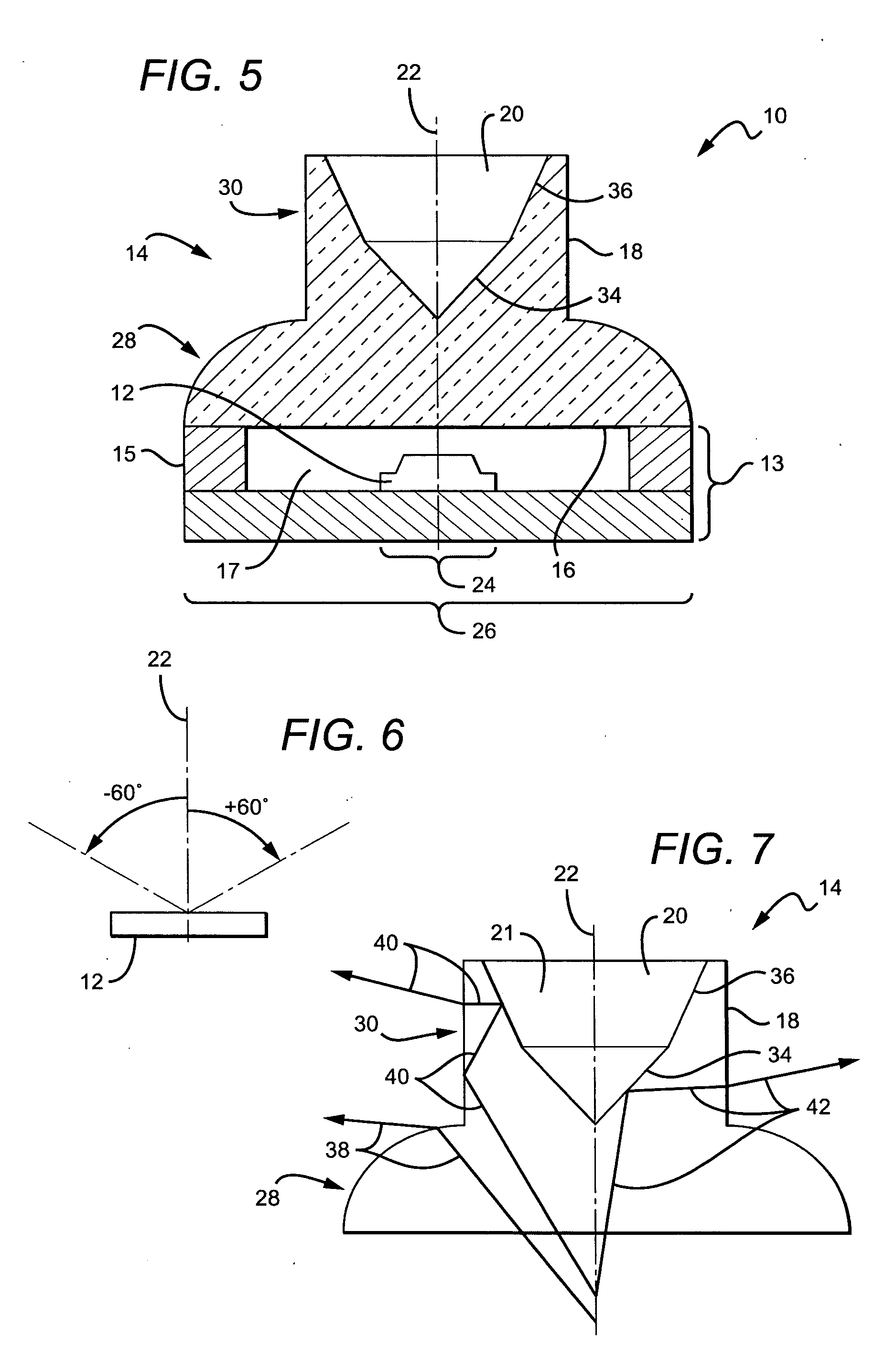
[0026] The present invention provides light emitting diode (LED) packages and lenses that cause the light emitted from a light source to be substantially sideways emitted from the package instead of forward emitted. Such an LED package includes an LED structure that outputs light in a pattern about an axis and an optical coupling device or lens with a central axis. The coupling device is positioned relative to the LED structure and accepts light from the LED. The coupling device includes a first dielectric interface surface that is substantially cylindrical with respect to the central axis, and a reflecting surface. The first dielectric interface surface accepts a first portion of light from the LED structure and directs it toward the reflecting surface. The reflecting surface accepts the light from the first dielectric interface surface and directs it back toward the first dielectric interface surface as opposed to allowing the light to pass through the reflecting surface. The ligh...


PUM


Abstract

An LED package includes a LED structure that outputs light in a pattern about an axis and an optical coupling device with a central axis. The coupling device is positioned relative to the LED structure and accepts light from the LED. The coupling device includes a first dielectric interface surface that is substantially cylindrical with respect to the central axis, and a reflecting surface. The first dielectric interface surface accepts a first portion of light from the LED structure and directs it toward the reflecting surface. The reflecting surface accepts the light from the first dielectric interface surface and directs it toward the first dielectric interface surface in a direction substantially perpendicular to the central axis.

Description

RELATED APPLICATION DATA [0001] This application claims the benefit U.S. Provisional Application Ser. No. 60 / 618,081 filed Oct. 12, 2004.BACKGROUND OF THE INVENTION [0002] 1. Field of the Invention [0003] This invention relates to light emitting diode (LED) packages and more particularly to side-emitting LEDs. [0004] 2. Description of Related Art [0005] As illustrated in FIG. 1, many light sources, including many light emitting diode (LED) semiconductor die, produce light in a Lambertian radiation pattern with respect to an axis perpendicular to the base plane of the die. The majority of the light leaving the die is substantially forwardly directed, although much of it is at a wide angle. Many applications, however, require substantially all light to be directed at a wide angle, approaching or somewhat exceeding 90°, with little or no light at forward angles. [0006] In order to obtain a wide angle distribution of light from an LED package, a side-directing lens configured to redirec...

Claims


Application Information

Patent Timeline
IPC IPC(8): H01L33/00H01L21/00H01L29/22H01L33/54H01L33/58H01L33/60
CPCG02B6/4214H01L33/54H01L33/58H01L33/60F21K9/52G02B19/0028G02B19/0061F21K9/50G02B19/0071F21Y2115/10F21K9/60F21K9/61H01L33/483H01L33/52
Inventor KELLER, BERNDJACOBSON, BENJAMINGENGELBACH, ROBERT
Owner CREELED INC
Why Eureka
Try Eureka