Anomaly detector for vibratory angular rate sensor

Inactive Publication Date: 2006-04-13
DENSO CORP
View PDF3 Cites 9 Cited by
  • Summary
  • Abstract
  • Description
  • Claims
  • Application Information

AI Technical Summary

Benefits of technology

[0009] It is therefore an object of the present invention to enable quick detection of a gradually varying anomaly of a DC component of an oscillation signal.

Problems solved by technology

The differential output has a DC offset voltage, which win become abnormal when the bonding wire between the sensor and the differential amplifier is broken, for example.
However, the use of large time-constant low-pass filter will introduce a timing delay in detecting an abnormal offset voltage.
If a gradually varying anomaly occurs, the prior art detector cannot quickly detect the fault due to the introduced timing delay.
Further, with such a low-pass filter the time constant value may be large in comparison with the varying rate of a transient abnormal offset voltage.

Method used


Image

  • Anomaly detector for vibratory angular rate sensor
  • Anomaly detector for vibratory angular rate sensor
  • Anomaly detector for vibratory angular rate sensor

Examples


first embodiment

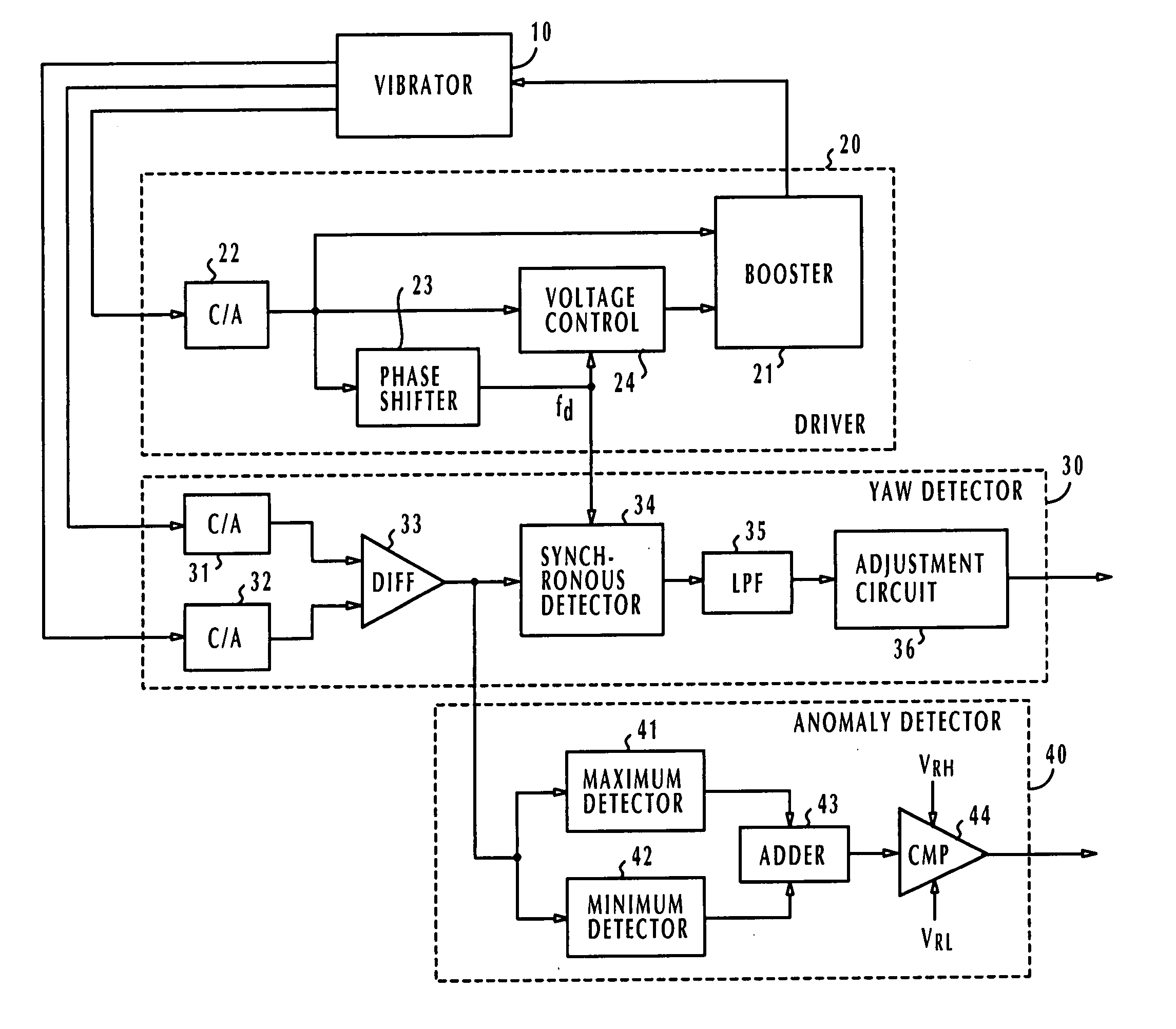
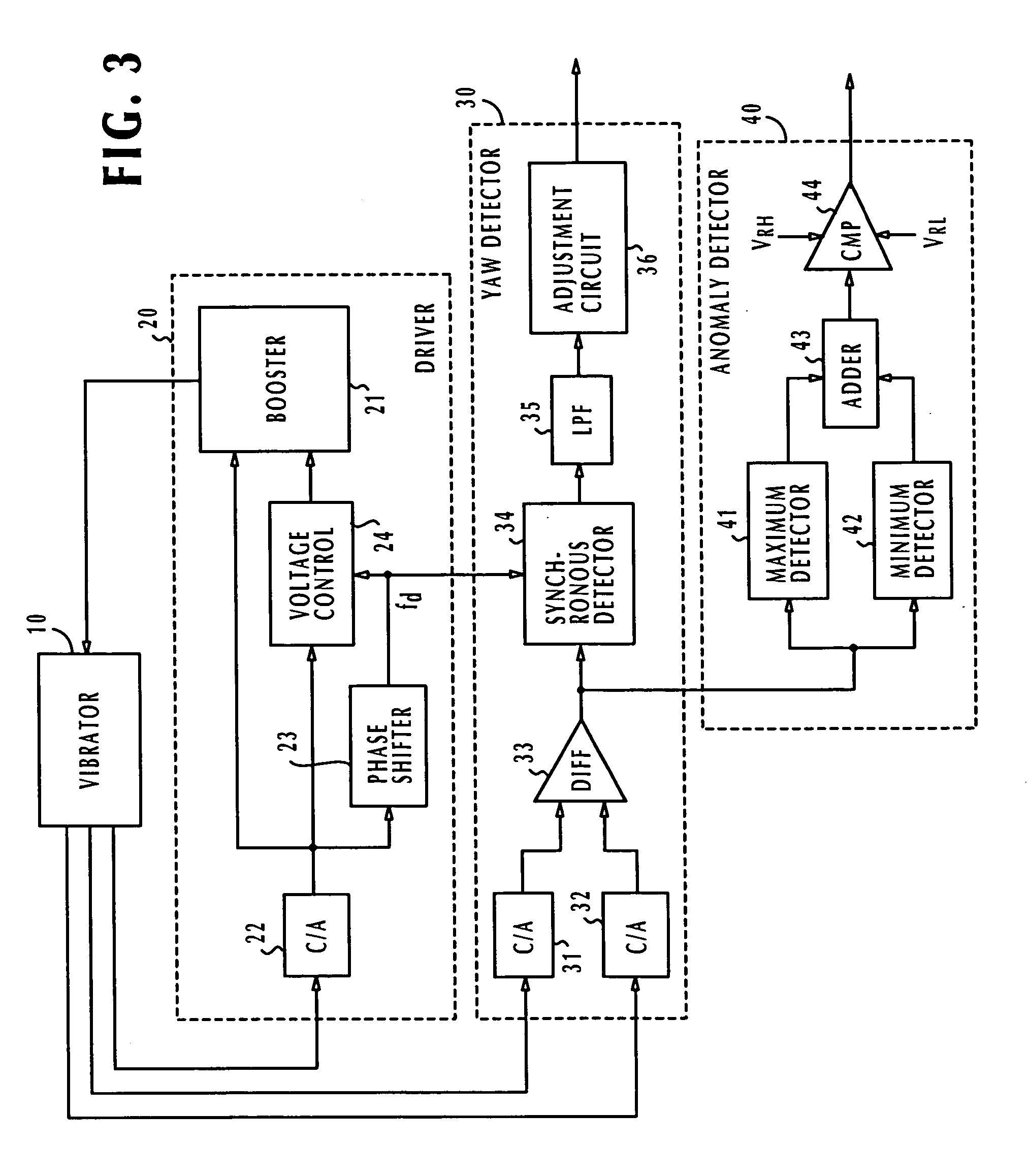
[0029] In FIG. 3, a vibratory angular rate sensor is illustrated as one exemplary sensing circuit for which an anomaly detector according to the present invention is provided.

[0030] The vibratory angular rate sensor comprises a vibrator 10, a driver 20 and a yaw detector 30. Vibrator 10 has a pair of yaw sensing elements and a driving element, not shown. The driving element is driven by the driver 20 to produce mechanical oscillations. If a yaw motion is generated, the sensing elements are caused to vibrate by the Coriolis force, producing a pair of oscillation signals. In addition, the vibrator 10 produces a monitoring signal indicating whether the driving element is operating properly.

[0031] Driver 20 includes a charge amplifier 22 that converts the monitoring signal to a voltage and supplies the voltage to a booster 21 that drives the vibrator 10. A phase shifter 23 is provided to compensate for the timing difference between the output of booster 21 and the monitoring signal fro...

second embodiment

[0048]FIG. 8 shows the present invention in which elements corresponding to those of FIG. 3 are marked with the same numerals and the description thereof is omitted.

[0049] The anomaly detector of the second embodiment, designated 50, essentially comprises an AC component detector that converts the oscillation signal to a pair of first and second signals of alternating amplitudes opposite in phase to each other. The anomaly detector 40 further includes a canceller that combines the first and second signals so that the opposite-phase alternating amplitudes are cancelled to detect the DC component (Vdc).

[0050] Specifically, in the second embodiment, the AC component detector includes a high-pass filter 51 which produces a first signal Va sin (ωdt+π) by high-pass filtering the oscillation signal and a second signal Va sin ωdt+Vdc which is the oscillation signal itself. The canceller comprises an adder 52 that receives the first signal from the high-pass filter 51 and the second signal ...


PUM


Abstract

In an anomaly detector that detects an abnormal condition of an oscillation signal of a circuit such as a vibratory sensing circuit, the oscillation signal, having AC and DC components, is converted to a pair of first and second signals of either opposite-polarity DC amplitudes or opposite-phase alternating amplitudes. The first and second signals are combined to cancel the AC component of the oscillation signal to detect the DC component. The DC component is then compared with the upper and lower thresholds of a decision range to produce an alarm if the DC component goes outside the decision range. In one embodiment, the first and second signals are produced by detecting positive and negative peak values of the oscillation signal at intervals. In a second embodiment, the first signal is produced by high-pass filtering the oscillation signal as a replica of the AC component and the second signal is the oscillation signal itself.

Description

CROSS-REFERENCE TO RELATED APPLICATIONS [0001] This application is based on Japanese Patent Applications No. 2004-296097, filed Oct. 8, 2004 and No. 2004-376270, filed Dec. 27, 2004, which are incorporated herein by reference. BACKGROUND OF THE INVENTION [0002] 1. Field of the Invention [0003] The present invention relates to vibratory angular sensors and more specifically to an anomaly detector for the vibratory angular sensors. [0004] 2. Description of the Related Art [0005] A known vibratory angular rate sensor is provided with a differential amplifier for producing a differential output indicating the difference between the outputs of a pair of sensing elements (or gyro-sensor). A predetermined frequency component is detected from the differential output using a synchronous detector and a low-pass filter. The differential output has a DC offset voltage, which win become abnormal when the bonding wire between the sensor and the differential amplifier is broken, for example. For t...

Claims


Application Information

Patent Timeline
IPC IPC(8): H03B1/00G01C19/5649
CPCG01C19/5649
Inventor TSURUHARA, TAKAOITO, HAJIMEMASE, SHUNJI
Owner DENSO CORP
Why Eureka
Try Eureka