
Swimming pool water monitoring device and method

Active Publication Date: 2022-05-31
DAMAR SUPPLIES LTD
View PDF13 Cites 0 Cited by
  • Summary
  • Abstract
  • Description
  • Claims
  • Application Information

AI Technical Summary

Benefits of technology

The present invention provides a water monitoring device that has improved data collection by monitoring both the small sample of water that has been exposed to treatment members (e.g. filters, pumps, heaters etc.) and the main body of water. The device can measure properties in both the main body of water and the water being fed into it, thus detecting changes faster. The device can also monitor bubbles, sound waves, chemical composition and water level, amongst others. It uses an optical module (e.g. camera) to monitor the water inlet / outlet channel and a hydro-sonic module to detect intrusions. The device can also use sonic waves to detect the water level and cover of the pool. Overall, the device provides a more comprehensive and accurate monitoring of water quality and circulation.

Problems solved by technology

Such systems however require that the user is in proximity of the body of water and provides limited information that is correct only at the point of use.
These known testing or monitoring systems typically only monitor basic water conditions and do not monitor, for example, filter, pump or heater efficiency or pool occupancy etc.

Method used


Image

  • Swimming pool water monitoring device and method
  • Swimming pool water monitoring device and method
  • Swimming pool water monitoring device and method

Examples


first embodiment

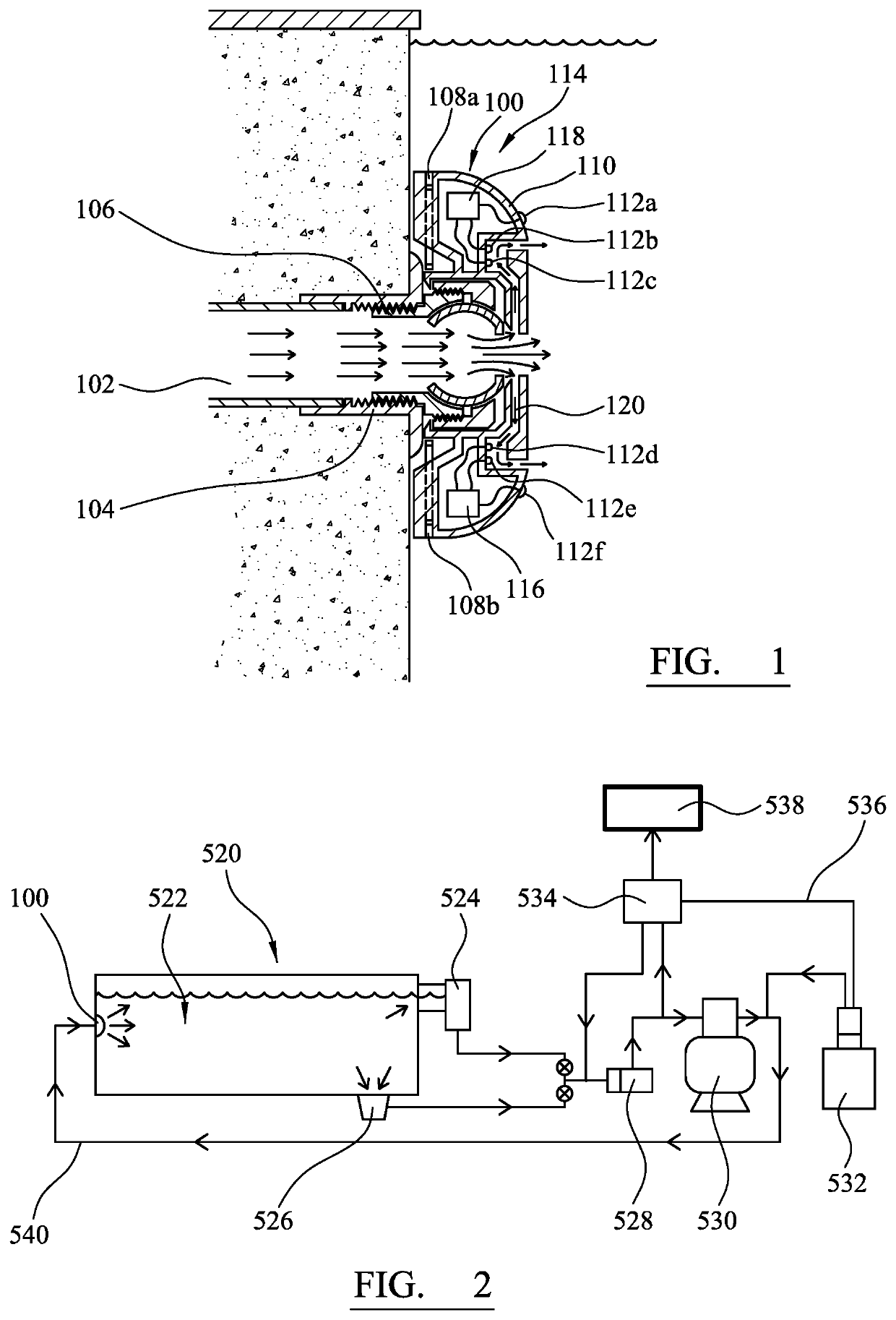
[0072]FIG. 1 shows a schematic representation of a water monitoring device according to the present invention arranged in a swimming pool.

second embodiment

[0073]FIG. 2 shows a schematic representation of a water management apparatus according to the present invention containing the device of FIG. 1.

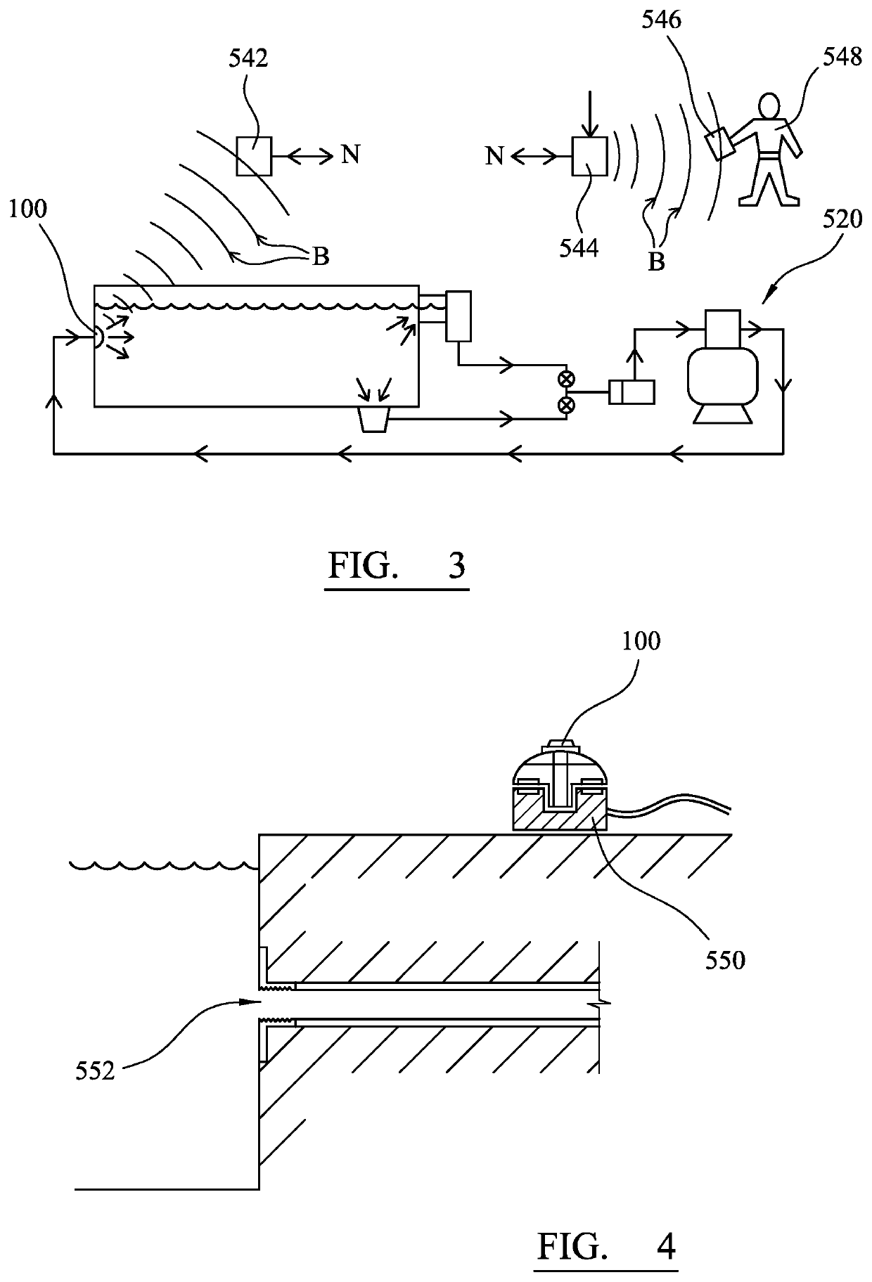
[0074]FIG. 3 shows a schematic representation of the water management apparatus according to FIG. 2.

[0075]FIG. 4 shows a schematic representation of the water monitoring device of FIG. 1 arranged on a charging member.

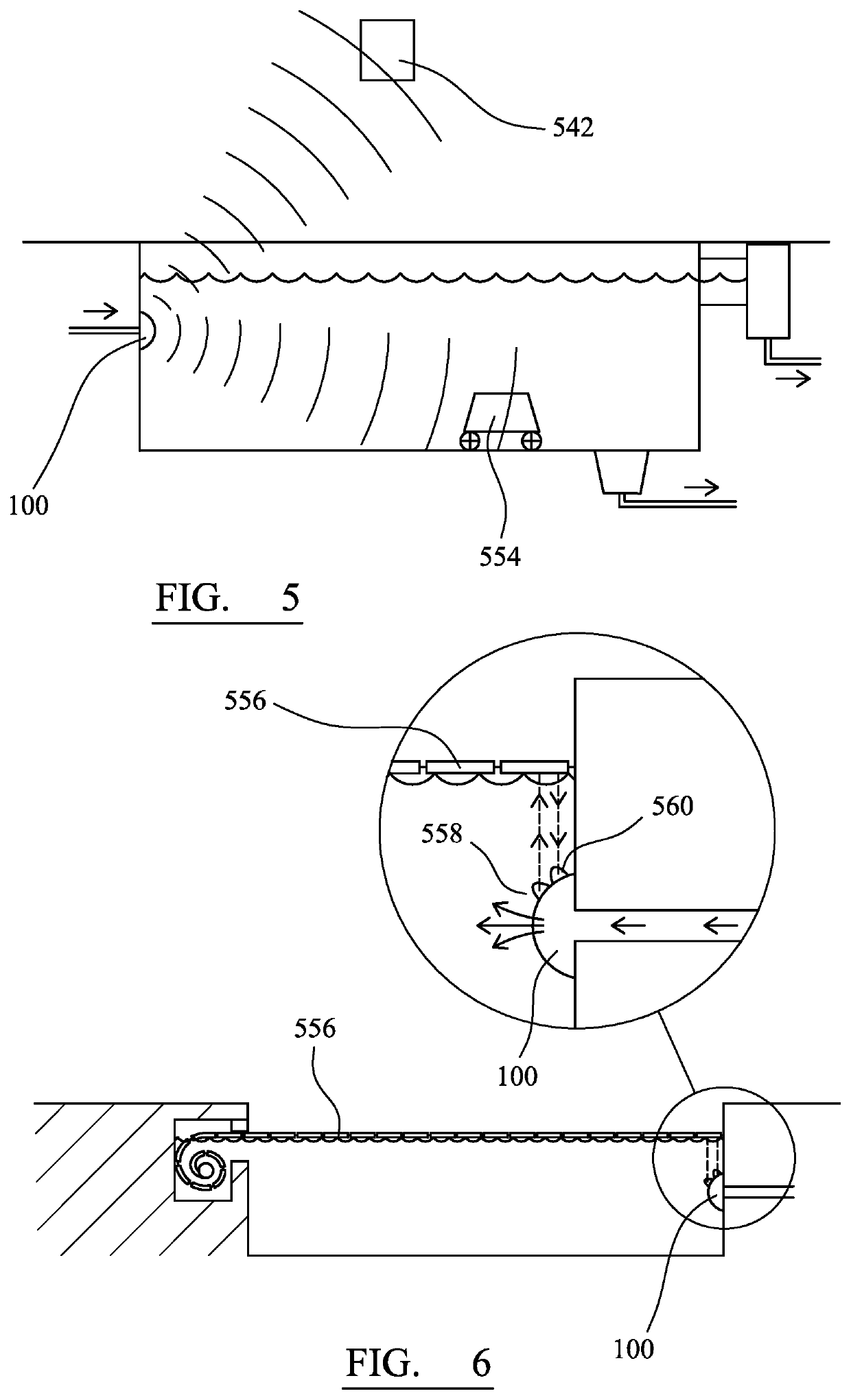
[0076]FIG. 5 shows a schematic representation of the water managing apparatus according to FIG. 2 and a robot cleaner.

[0077]FIG. 6 shows a schematic representation of the water monitoring device of FIG. 1 arranged in a swimming pool having a pool cover.

[0078]FIG. 7 shows a schematic representation of a second embodiment of a water monitoring device according to the present invention.

third embodiment

[0079]FIG. 8 shows a schematic representation of a water monitoring device according to the present invention.

DETAILED DESCRIPTION OF THE DRAWINGS

[0080]FIG. 1 shows a water monitoring device (100) removably attached adjacent to a water inlet (102) of a swimming pool. The water inlet (102) has a threaded section (104) which is threadedly engaged with a corresponding threaded section (106) on the water monitoring device (100) such that the water monitoring device (100) is held in a substantially stationary position adjacent to the water inlet (102). The water monitoring device (100) has a housing (110) formed from plastic. The water monitoring device (100) has six sensors (112a-t); two of which (112a, 112f) are located on the outside of the housing (110) in the main body of water (114) of the swimming pool and four of which (112b, 112c, 112d, 112e) are located on the inside of the housing (110) adjacent to the water inlet (102). The water monitoring device (100) includes a battery (11...


PUM


Abstract

There is described a water monitoring device for monitoring a body of water. The body of water comprises a main body of water and a water inlet and / or water outlet. The water monitoring device comprises a sensor operable to generate data in relation to a property of the body of water, an attachment member operable to removably arrange the device in a substantially stationary position adjacent to the water inlet and / or water outlet of the body of water; and a communication member operable to transmit the data relating to a property of the body of water to a remote device. Also described is a water monitoring apparatus and a method of monitoring a body of water.

Description

CROSS REFERENCE TO RELATED PATENT APPLICATIONS[0001]This application claims the benefit of and priority to PCT / GB2018 / 051037 filed Apr. 19, 2018 which claims the benefit of and priority to Great Britain Application No. 1706168.0 filed on Apr. 19, 2017.TECHNICAL FIELD AND BACKGROUND OF THE INVENTION[0002]The present invention relates to a water monitoring device. More specifically, the present invention relates to a water monitoring device for monitoring a body of water, in particular, for monitoring swimming pools. The invention also extends to a water management apparatus including the water monitoring device.[0003]Bodies of water, such as swimming pools, can require regular maintenance in order to preserve appropriate conditions. It is desirable to be able to determine that properties such as water temperature, chemical levels, pH, pool cover performance and lighting performance are within the necessary parameters. If one or more of these properties is found to be above or below t...

Claims


Application Information

Patent Timeline
IPC IPC(8): C02F1/00C02F9/00E04H4/12E04H4/14E04H4/16G01N33/18C02F1/40C02F1/68C02F103/42
CPCC02F1/008C02F9/00E04H4/1209E04H4/129E04H4/1281E04H4/148E04H4/1654G01N33/18C02F1/001C02F1/40C02F1/685C02F2103/42C02F2201/009C02F2209/008C02F2209/02C02F2209/29G01N33/1886E04H4/14
Inventor BURNHAM, DOUGLAS
Owner DAMAR SUPPLIES LTD
Learn More