
Touch detectable display device and driving method thereof

a display device and display device technology, applied in the direction of instruments, computing, electric digital data processing, etc., can solve the problems of increasing the thickness and weight of the display device, difficult to represent minute characters or pictures, and the area where a touch may not be easily detected

Inactive Publication Date: 2006-04-13
SAMSUNG DISPLAY CO LTD
View PDF7 Cites 174 Cited by
  • Summary
  • Abstract
  • Description
  • Claims
  • Application Information

AI Technical Summary

Benefits of technology

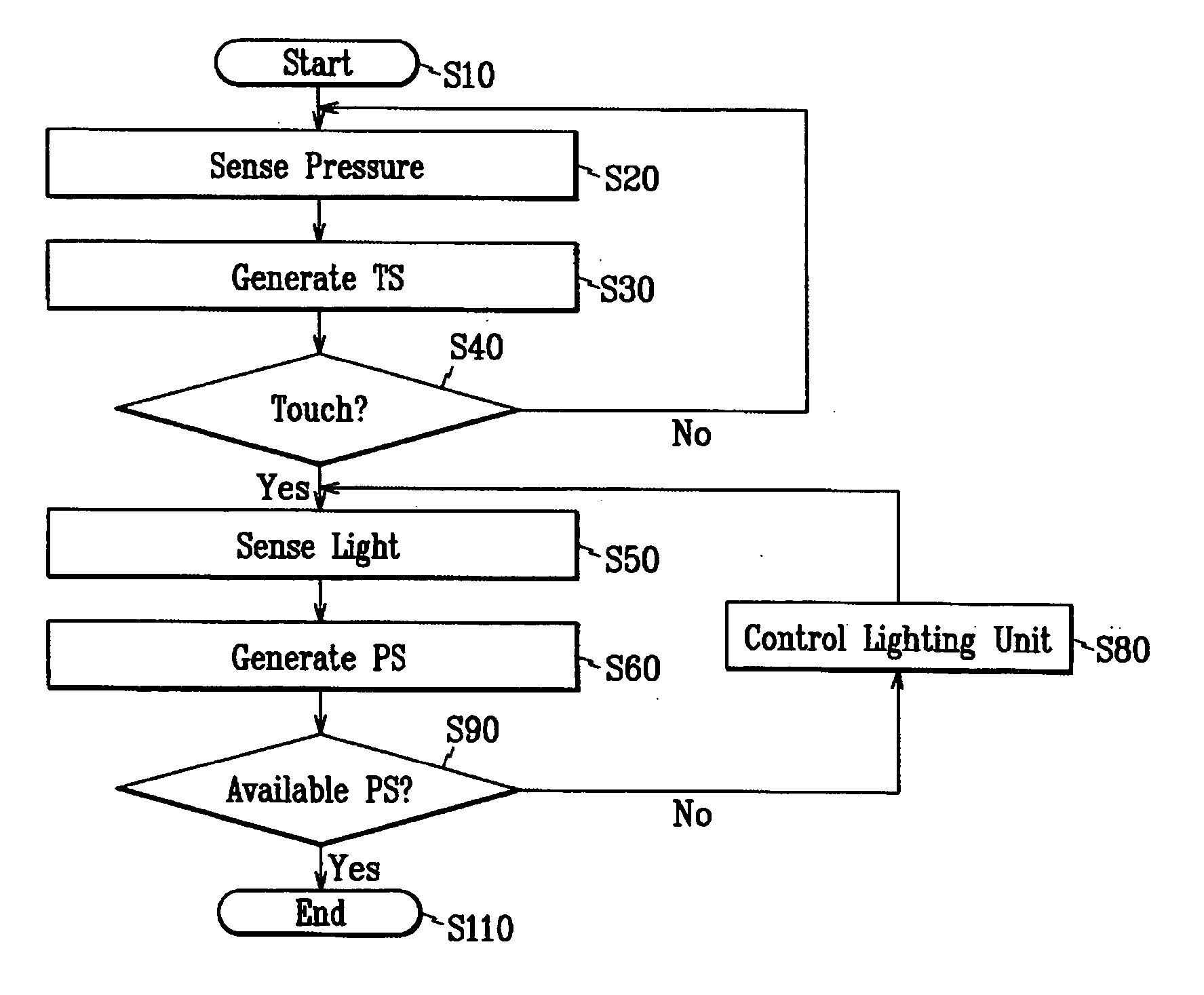
The present invention provides a display device with a lighting unit and a pressure sensing unit that can detect touch on the display panel. The device can determine if it is in a dead zone and adjust the lighting unit accordingly. The lighting control signal can adjust the luminance or the phase of the driving voltage of the lighting unit. The device can also determine the position of the touch based on the second sensing signal and adjust the timing for generating the second sensing signal accordingly. The technical effects of the invention include improved user experience and better control over the display device.

Problems solved by technology

Although the photosensors may be provided on an external device such as a touch screen panel to be attached to the LCD, it may increase the thickness and the weight of the LCD and it may make it difficult to represent minute characters or pictures.
However, such a photosensor generates an output that varies depending on a circumference such as the intensity of an external light or of a backlight lamp, and thus there is an area where a touch may not be easily detected.

Method used


Image

  • Touch detectable display device and driving method thereof
  • Touch detectable display device and driving method thereof
  • Touch detectable display device and driving method thereof

Examples


Embodiment Construction

[0036] The present invention is described below more fully with reference to the accompanying drawings, in which preferred embodiments of the invention are shown.

[0037] In the drawings, the thickness of layers and regions are exaggerated for clarity. Like numerals refer to like elements throughout. It will be understood that when an element such as a layer, region or substrate is referred to as being “on” another element, it can be directly on the other element or intervening elements may also be present. In contrast, when an element is referred to as being “directly on” another element, there are no intervening elements present.

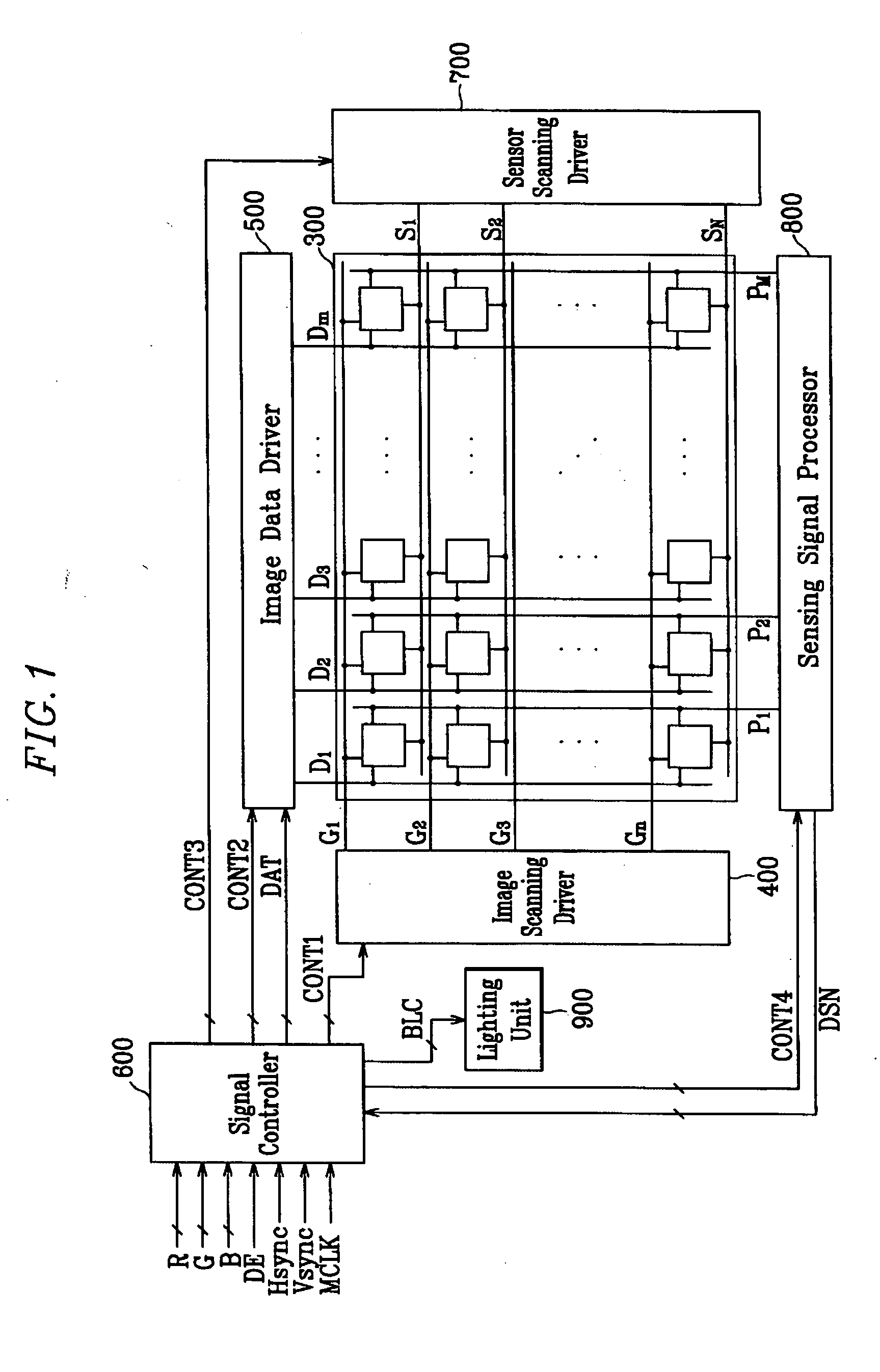
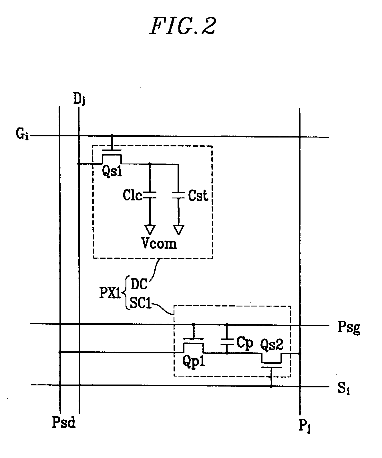
[0038] A liquid crystal display according to an embodiment of the present invention is described below in detail with reference to FIGS. 1, 2 and 3.

[0039]FIG. 1 is a block diagram of an LCD according to an embodiment of the present invention, FIG. 2 is an equivalent circuit diagram of a pixel including a light sensing circuit for an LCD according to an em...


PUM


Abstract

A display device is disclosed which includes: a display panel; a lighting unit to illuminate the display panel and having a state in response to a lighting control signal; a pressure sensing unit generating a first sensor output signal according to a touch on the display panel; a light sensing unit receiving light from the lighting unit and ambient light and generating a second sensor output signal according to the touch on the display panel; a sensor scanning driver outputting sensor scanning signals to the pressure sensing unit and the light sensing unit in response to a sensor scanning control signal; and a sensing controller generating the lighting control signal and the sensor scanning control signal based on the first and the second sensor output signals and outputting the lighting control signal to the lighting unit and the sensor scanning control signal and the sensor scanning driver.

Description

BACKGROUND OF THE INVENTION [0001] (a) Field of the Invention [0002] The present invention relates to a display device and a driving method thereof and in particular, a touch detectable display device and a driving method thereof. [0003] (b) Description of Related Art [0004] A liquid crystal display (LCD) includes a pair of panels provided with pixel electrodes and a common electrode and a liquid crystal layer with dielectric anisotropy interposed between the panels. The pixel electrodes are arranged in a matrix and connected to switching elements such as thin film transistors (TFTs) such that they receive image data voltages row by row. The common electrode covers entire surface of one of the two panels and it is supplied with a common voltage. A pixel electrode and corresponding portions of the common electrode, and corresponding portions of the liquid crystal layer form a liquid crystal capacitor that as well as a switching element connected thereto is a basic element of a pixel....

Claims


Application Information

Patent Timeline
Patent Type & Authority Applications(United States)
IPC IPC(8): G09G5/00
CPCG06F3/0412G06F3/0414G06F3/042G06F2203/04106G02F1/133
Inventor PARK, SANG-JINUH, KEE-HANLEE, MYUNG-WOOLEE, JOO-HYUNG
Owner SAMSUNG DISPLAY CO LTD
Learn More