Fundus camera having scanned illumination and pupil tracking

a technology of illumination and pupil tracking, applied in the field of electronic imaging apparatus for fundus imaging, can solve the problems of high cost and complexity, difficult operation, and significant hurdles to widespread acceptance and usability of these devices, and achieve the effect of reducing or eliminating the requirement for pupil dilation and a larger field of view

Inactive Publication Date: 2006-04-13
CARESTREAM HEALTH INC
View PDF9 Cites 53 Cited by
  • Summary
  • Abstract
  • Description
  • Claims
  • Application Information

AI Technical Summary

Benefits of technology

[0011] It is an advantage of the present invention that it minimizes or eliminates the requirement for pupil dilation for fundus imaging.
[0012] It is a further advantage of the present invention that it provides the capability for full-color fundus imaging.
[0013] It is yet a further advantage of the present invention that it provides a fundus imaging system with a larger field of view than conventional systems.
[0014] These and other objects, features, and advantages of the present invention will become apparent to those skilled in the art upon a reading of the following detailed description when taken in conjunction with the drawings wherein there is shown and described an illustrative embodiment of the invention.

Problems solved by technology

While these patents attest to continuous improvements in fundus camera design, there are still significant hurdles to widespread acceptance and usability of these devices.
Among disadvantages noted with current devices are high cost and complexity, difficulty of operation, large size, and image quality limitations.
These disadvantages hinder the successful deployment of fundus cameras in primary care physician (PCP) offices or in medical test labs, where they could be used by a technician having relatively little training in device operation and imaging, to obtain images that can be assessed by specialists at some other location.
A further significant disadvantage of existing fundus imaging apparatus relates to the requirement for pupil dilation.
At best, pupil dilation is uncomfortable and at least temporarily unsettling; at worst, dilation can even be dangerous for some individuals.
However, in practice, pupil dilation is still often required when using these apparatus.

Method used


Image

  • Fundus camera having scanned illumination and pupil tracking
  • Fundus camera having scanned illumination and pupil tracking
  • Fundus camera having scanned illumination and pupil tracking

Examples


Embodiment Construction

[0033] The present description is directed in particular to elements forming part of, or cooperating more directly with, apparatus in accordance with the invention. It is to be understood that elements not specifically shown or described may take various forms well known to those skilled in the art.

Conventional Illumination Arrangement

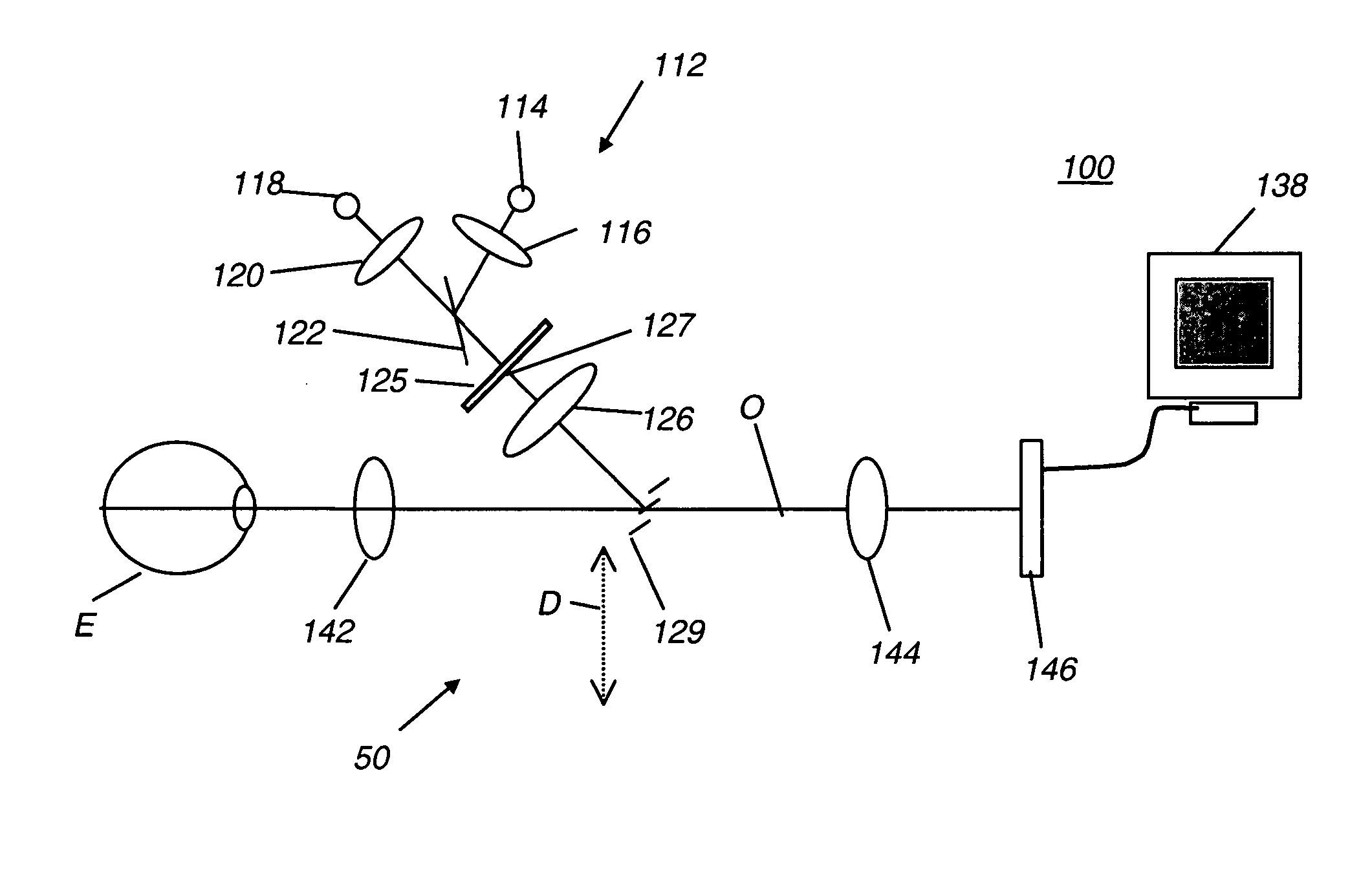
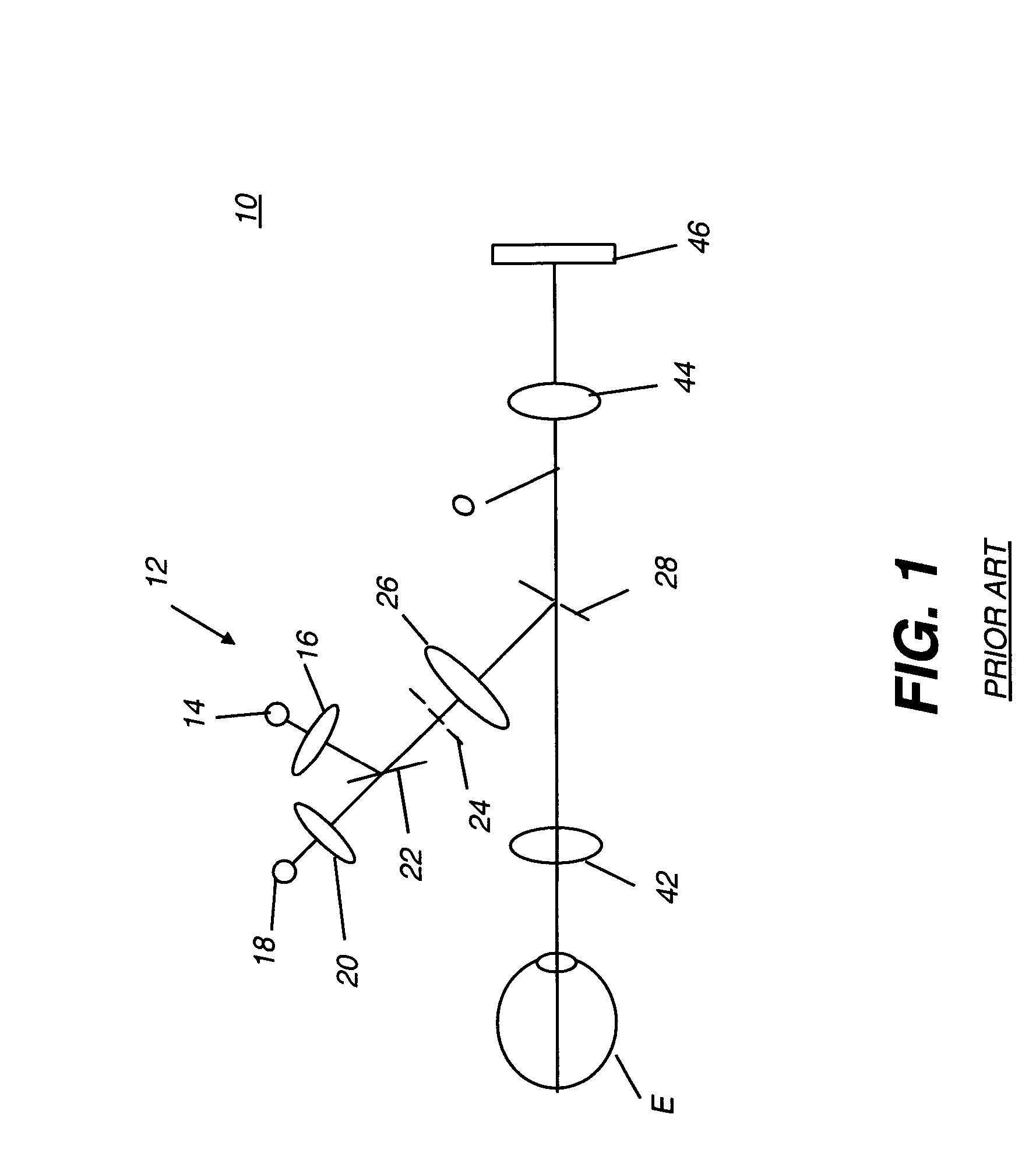
[0034] In order to more fully appreciate the improved apparatus and method of the present invention, it is first instructive to review, at a high level, the operation of the illumination subsystem in a conventional fundus imaging apparatus. Referring to FIG. 1, there is shown a fundus imaging apparatus 10 in which a conventional illumination section 12 is used. The patient's eye E is positioned along an optical axis O using an alignment subsystem, not shown in FIG. 1, but described subsequently. Illumination section 12 directs light either from an observation light source 14 and a lens 16 or from an image capture light source 18 and a lens 20 as cont...


PUM


Abstract

An apparatus (100) for obtaining an image of the eye, has an alignment section (160) for aligning the pupil of the eye along an optical axis and a pupil sensor (170) for identifying pupil location and dimensions. An illumination section (112) has a light source (114) for providing an illumination beam and a spatial light modulator (125) for positioning and shaping the illumination beam according to the sensed location and dimensions of the pupil. An illumination beam partitioning mechanism (50) segments the illumination beam directed toward the pupil of the eye into at least one light-bearing segment (150) and at least one blocked segment. An actuator (132) coupled to the illumination beam partitioning mechanism (50) scans the at least one light-bearing segment (150) of the illumination beam across the pupil of the eye. An image sensor (146), aligned along the optical axis, obtains reflected light from the eye.

Description

FIELD OF THE INVENTION [0001] This invention generally relates to electronic imaging apparatus for fundus imaging and more particularly relates to an improved fundus imaging apparatus using scanned slit illumination and an electronically controlled aperture. BACKGROUND OF THE INVENTION [0002] Fundus camera imaging is acknowledged to be an important diagnostic tool for detection of various conditions affecting the eye, including diabetic retinopathy and macular degeneration. Various embodiments of fundus imaging apparatus are disclosed, for example in U.S. Pat. Nos. 5,713,047 (Kohayakawa); 5,943,116 (Zeimer); 5,572,266 (Ohtsuka); 4,838,680 (Nunokawa); 6,546,198 (Ohtsuka); and 6,636,696 (Saito). [0003] While these patents attest to continuous improvements in fundus camera design, there are still significant hurdles to widespread acceptance and usability of these devices. Among disadvantages noted with current devices are high cost and complexity, difficulty of operation, large size, a...

Claims


Application Information

Patent Timeline
Patent Type & Authority Applications(United States)
IPC IPC(8): A61B3/10A61B3/14A61B3/00
CPCA61B3/12A61B3/15
Inventor LIANG, RONGGUANGKESSLER, DAVID
Owner CARESTREAM HEALTH INC
Why Eureka
Try Eureka