Fundus imaging system

a technology of fundus imaging and imaging system, which is applied in the field of electronic imaging apparatus for fundus imaging, can solve the problems of high cost and complexity, difficult operation, and significant hurdles to widespread acceptance and usability of these devices, and achieve the effect of reducing or eliminating the requirement of pupil dilation and a larger field of view

Inactive Publication Date: 2007-07-10
CARESTREAM HEALTH INC
View PDF7 Cites 10 Cited by
  • Summary
  • Abstract
  • Description
  • Claims
  • Application Information

AI Technical Summary

Benefits of technology

[0030]It is an advantage of the present invention that it minimizes or eliminates the requirement for pupil dilation for fundus imaging.
[0031]It is a further advantage of the present invention that it provides the capability for full-color fundus imaging.
[0032]It is yet a further advantage of the present invention that it provides a fundus imaging system with a larger field of view than conventional systems.
[0033]It is yet a further advantage of the present invention that it allows straightforward operation by a non-specialist, without requiring extensive operator training.

Problems solved by technology

While these patents attest to continuous improvements in fundus camera design, there are still significant hurdles to widespread acceptance and usability of these devices.
Among disadvantages noted with current devices are high cost and complexity, difficulty of operation, large size, and image quality limitations.
These disadvantages hinder the successful deployment of fundus cameras in primary care physician (PCP) offices or in medical test labs, where they could be used by a technician having relatively little training in device operation and imaging, to obtain images that can be assessed by specialists at some other location or at some later time.
A further significant disadvantage of existing fundus imaging apparatus relates to the requirement for pupil dilation.
At best, pupil dilation is uncomfortable and at least temporarily unsettling; at worst, dilation can even be dangerous for some individuals.
However, in practice, pupil dilation is still often required when using these apparatus.
While it is known that, given a large population of individuals, there can be a range of pupil sizes and a variety of pupil shapes, conventional fundus imaging apparatus are not adaptable to individual eye geometries.
Little attempt is made to adapt camera operation to suit the particular characteristics of each individual eye.

Method used


Image

  • Fundus imaging system
  • Fundus imaging system
  • Fundus imaging system

Examples


Embodiment Construction

[0059]The present description is directed in particular to elements forming part of, or cooperating more directly with, apparatus in accordance with the invention. It is to be understood that elements not specifically shown or described may take various forms well known to those skilled in the art.

System Configuration

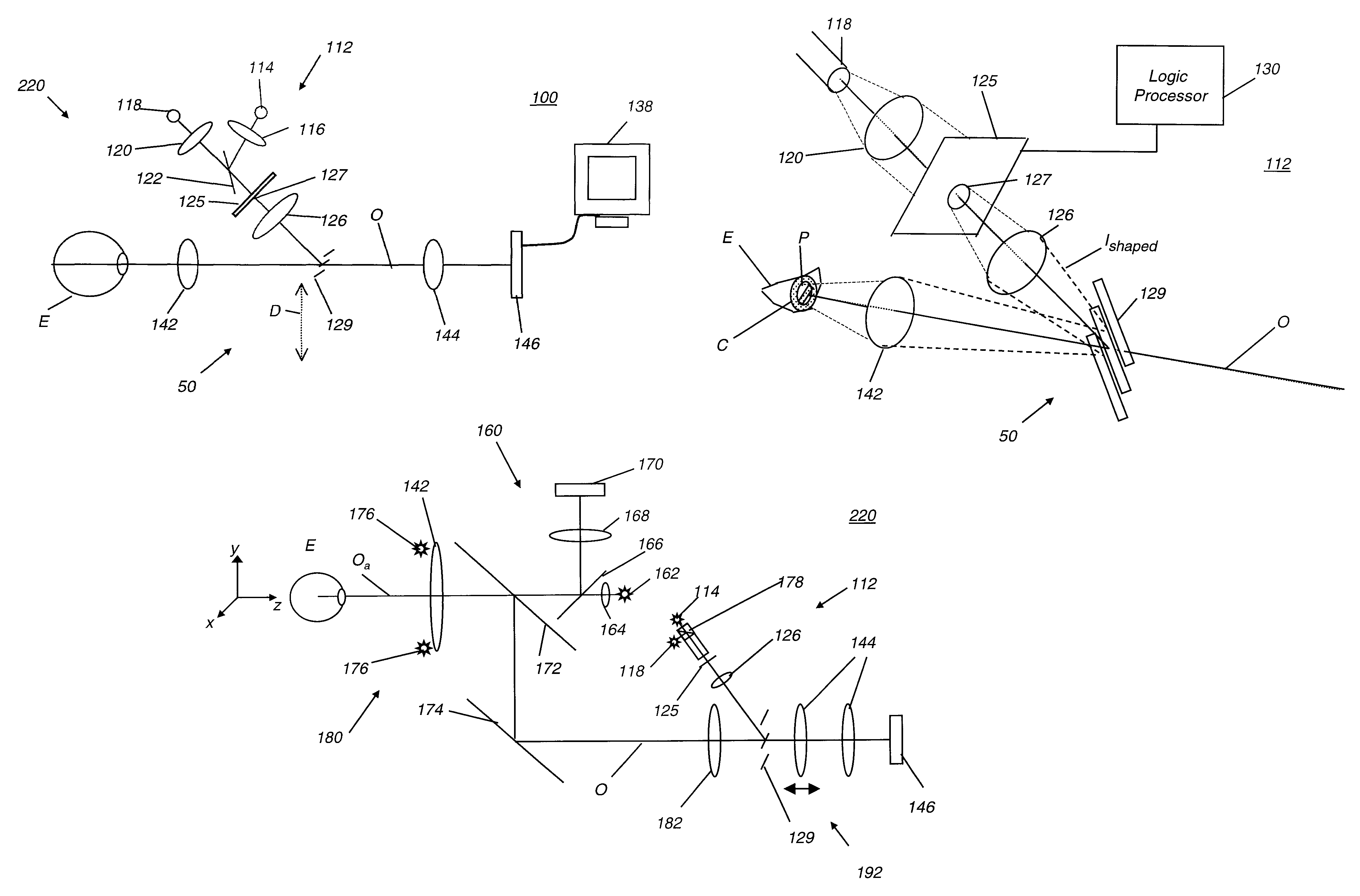
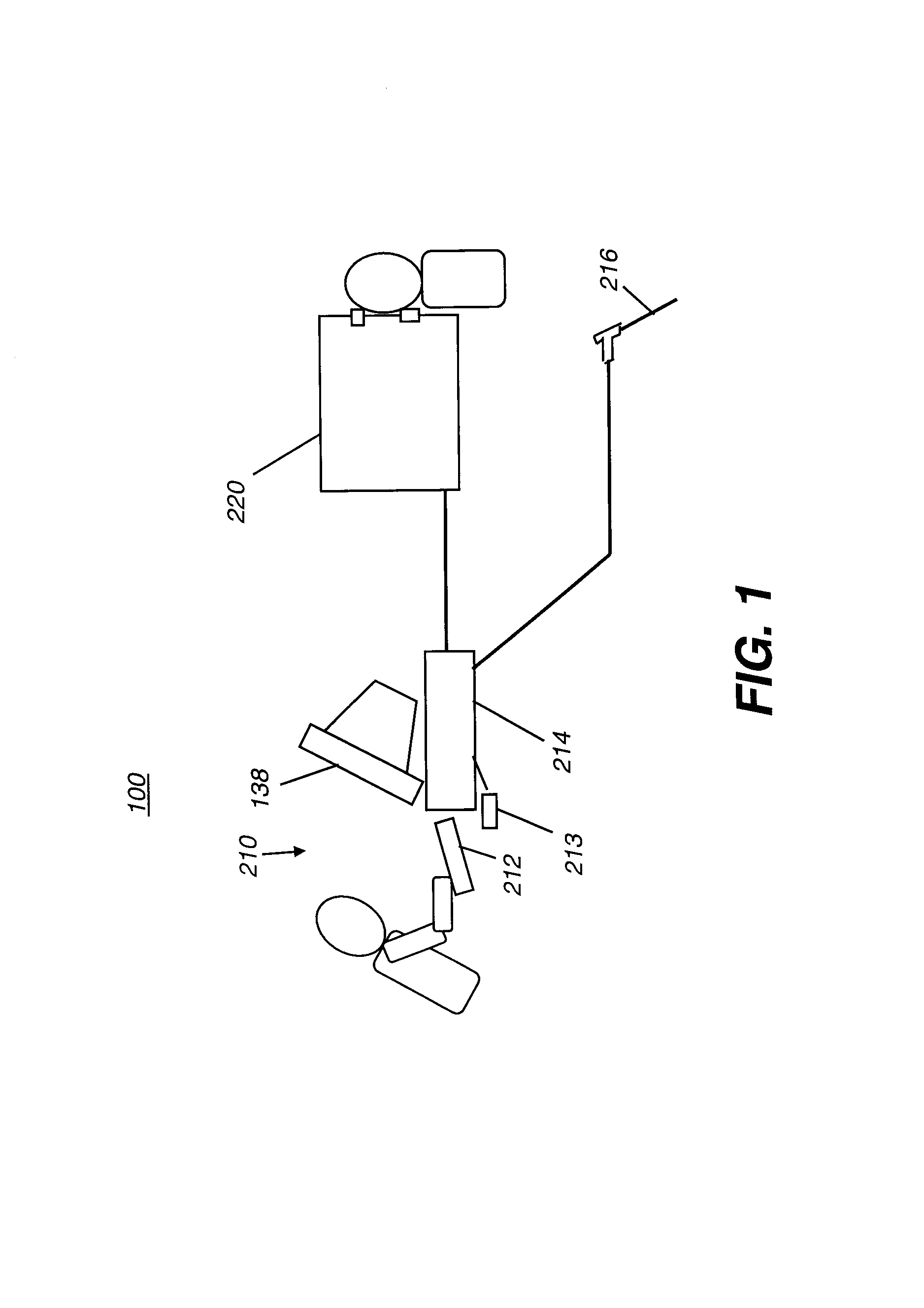
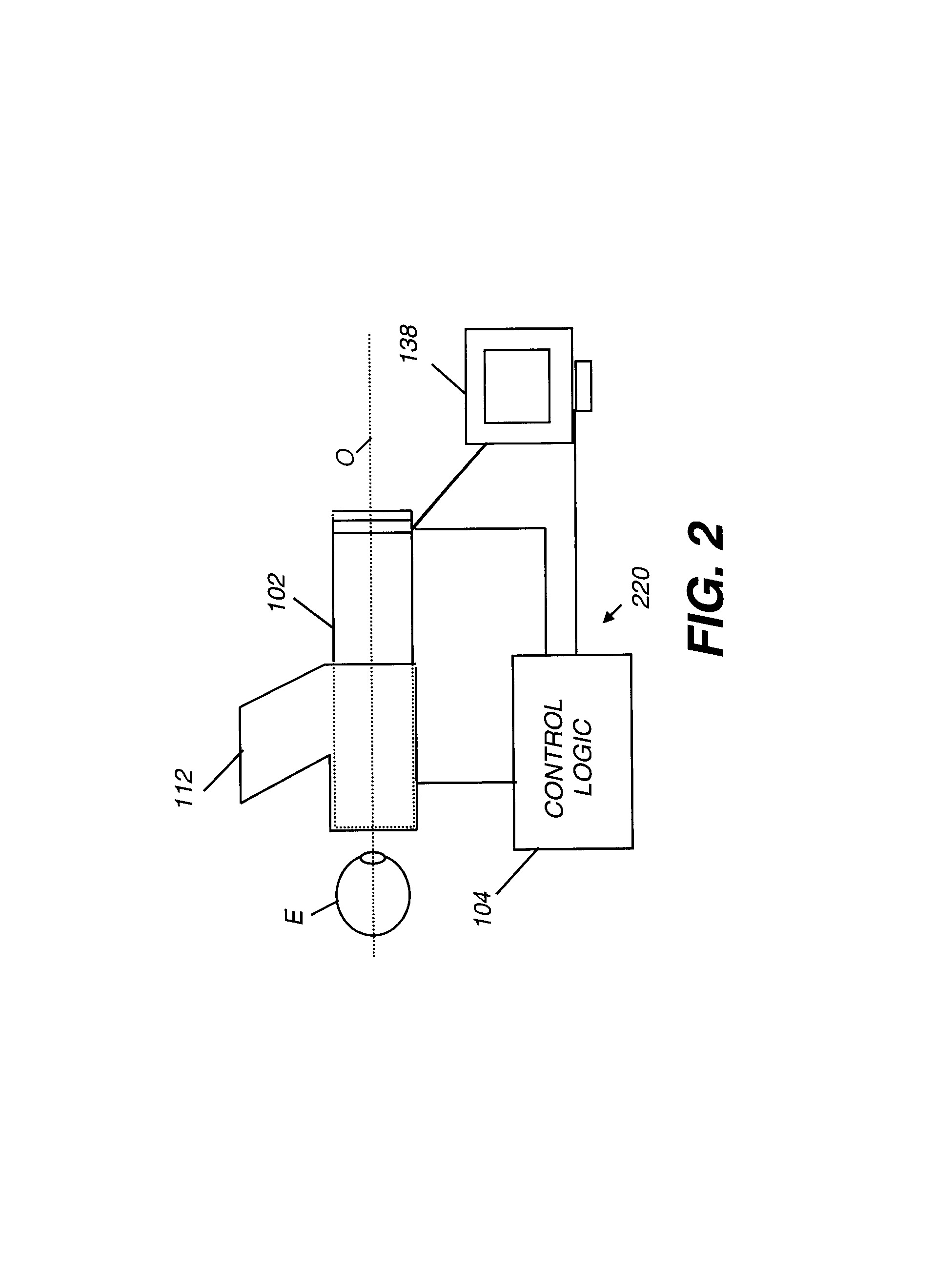
[0060]Referring to FIG. 1, there is shown a fundus imaging system 100 according to the present invention. To support fundus imaging system 100, a control workstation 210 has a display 138, a keyboard 212, and a control logic processor 214 for providing control logic and operator interface functions. Imaging functions are provided by optical, electro-optical, and electronic components within a fundus imaging appliance 220. A network 216 allows communication between fundus imaging system 100 and processing and storage devices at other networked sites. Using network 216, for example, fundus images obtained by fundus imaging system 100 can be uploaded to other sites, such a...


PUM


Abstract

An apparatus (220) for obtaining a scanned image of an eye has a reference locator for pupil alignment apparatus along an optical axis. A pupil profiling apparatus for obtaining an outline of the pupil has a pupil profiling light source (176), a sensor (170) for detecting reflected light, and a control logic processor (104) for computing an outline of the pupil according to detected light. An illumination apparatus (112) for directing visible illumination into the eye has a spatial light modulator (125) for shaping an illumination beam according to the detected outline, a scanning element (229), and a camera (146) for obtaining the scanned image by sensing a portion of the reflected illumination.

Description

CROSS REFERENCE TO RELATED APPLICATIONS[0001]Reference is made to commonly-assigned copending U.S. patent application Ser. No. 10 / 947,018, filed Sep. 22, 2004, entitled FUNDUS CAMERA HAVING SCANNED ILLUMINATION AND PUPIL TRACKING by Liang et al.; the disclosure of which is incorporated herein.FIELD OF THE INVENTION[0002]This invention generally relates to electronic imaging apparatus for fundus imaging and more particularly relates to an improved fundus imaging apparatus for non-mydriatic imaging using scanned slit illumination and an electronically controlled aperture, with automated operator controls and compensation for patient movement.BACKGROUND OF THE INVENTION[0003]Fundus camera imaging is acknowledged to be an important diagnostic tool for detection of various conditions affecting the eye, including diabetic retinopathy and macular degeneration. Various embodiments of fundus imaging apparatus are disclosed, for example in U.S. Pat. No. 5,713,047 (Kohayakawa); U.S. Pat. No. 5...

Claims


Application Information

Patent Timeline
Patent Type & Authority Patents(United States)
IPC IPC(8): A61B3/14
CPCA61B3/145A61B3/112
Inventor BAEK, SEUNG-HOBLANDING, DOUGLASS L.LIANG, RONGGUANGTUCKER, DALE L.HAWVER, JEFFERY R.
Owner CARESTREAM HEALTH INC
Why Eureka
Try Eureka