Manufacturing method of optical component and camera module
a manufacturing method and optical component technology, applied in the field of manufacturing methods of optical components, can solve the problems of low welding strength in relation to a large melting mark, troublesome adhesive management, and increased manufacturing cost, and achieve the effect of reducing the change of the position of the lens barrel and accurate fixing method
- Summary
- Abstract
- Description
- Claims
- Application Information
AI Technical Summary
Benefits of technology
Problems solved by technology
Method used
Image

Examples
embodiment 1
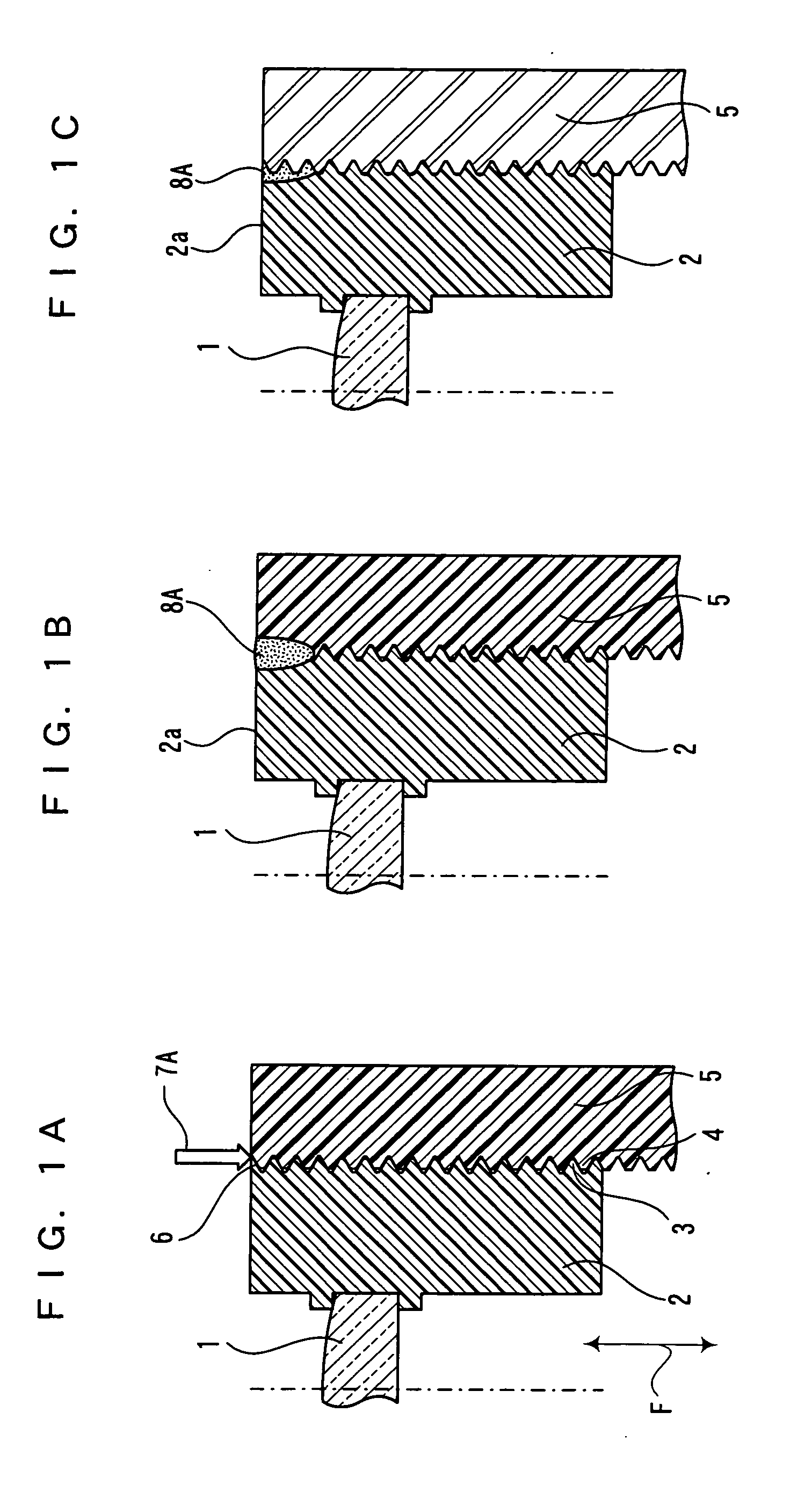
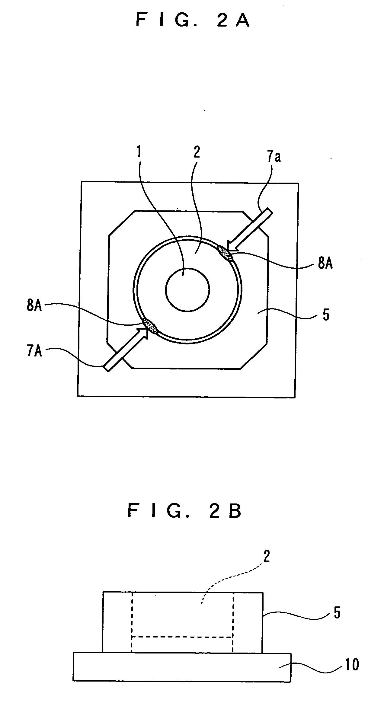
[0029]FIGS. 1A, 1B, 2A, and 2B show (Embodiment 1) of a manufacturing method of a camera module according to the present invention. The camera module has the following size: one side of a base part 10 is 11.0 mm and a thickness formed by the base part 10 and an outer lens barrel 5 is 6.0 mm.
[0030] A inner lens barrel 2 and the outer lens barrel 5 of FIG. 1A are both made of polycarbonate which is a thermoplastic resin. After focus adjustment in which the protrusion amount of the inner lens barrel 2 is adjusted by rotating the inner lens barrel 2 relative to the outer lens barrel 5, as shown in the plan view of FIG. 2A, a laser beam 7A is emitted over a joint 6 of a screwing part 3 of the inner lens barrel 2 and a screwing part 4 of the outer lens barrel 5 to fix the inner lens barrel 2 and the outer lens barrel 5 by welding.
[0031] At this point, the processing conditions of the laser beam 7A were an output of 0.2 to 1.5 W and irradiation time of 0.5 to 10.0 seconds. The laser beam...
embodiment 2
[0044]FIGS. 3 and 4 show (Embodiment 2) of a manufacturing method of a camera module according to the present invention.
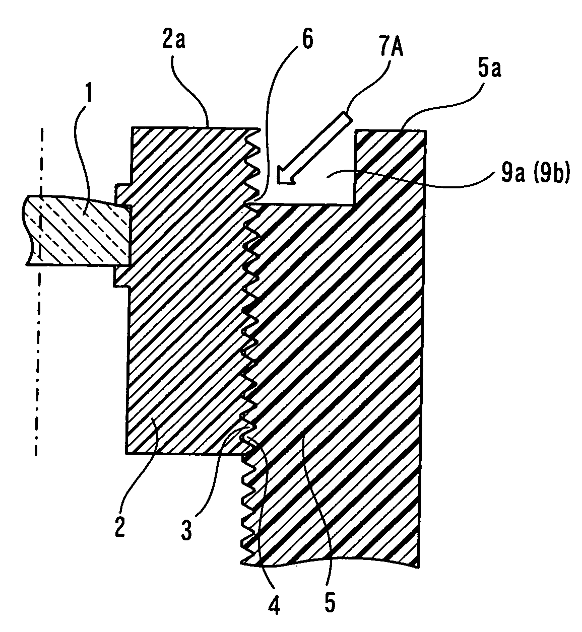
[0045] On an end face 5a of an outer lens barrel 5 of (Embodiment 2), laser beam passage openings 9a and 9b are formed with a phase difference of 180°. Each of the laser beam passage openings 9a and 9b has one end opened on the screwing part of the outer lens barrel 5 and the other end opened on the end face 5a of the outer lens barrel 5. Other components are made of the same materials in the same shapes as (Embodiment 1).
[0046] An inner lens barrel 2 and the outer lens barrel 5 are both made of polycarbonate.
[0047] After focus adjustment, a laser beam was emitted in a linear shape of about 0.7 mm×0.1 mm. Laser beams 7A were emitted simultaneously from diagonally above the outer lens barrel 5 with an angle of 35°±5° relative to the vertical axis and passed through the laser beam passage openings 9a and 9b with a depth of 1 mm and a width of 2 mm to melt and cure...
embodiment 3
[0056]FIGS. 5 and 6 show (Embodiment 3) of a manufacturing method of a camera module according to the present invention.
[0057] Laser welding was performed simultaneously on three points from laser beam passage openings 9a, 9b, and 9c as in (Embodiment 2) except that the laser beam passage openings 9a, 9b, and 9c on the three points of FIG. 5 were uniformly arranged at 120°. At this point, the welding strength was 12 to 20 N·cm.
[0058] As shown in FIG. 6, laser welding was performed simultaneously on three points in the same manner except that the laser beam passage openings 9a, 9b, and 9c on the three points are arranged at 100°, 100°, and 160°. At this point, the welding strength was 10 to 15 N·cm.
[0059] These results indicate that the welding strength gradually increases with the number of laser beam passage openings. Further, even when the number of laser beam passage openings is not changed, the laser beam passage openings arranged at uniform or almost uniform angles can achie...
PUM
| Property | Measurement | Unit |
|---|---|---|
| Length | aaaaa | aaaaa |
| Length | aaaaa | aaaaa |
| Length | aaaaa | aaaaa |
Abstract
Description
Claims
Application Information
 - Generate Ideas
- Intellectual Property
- Life Sciences
- Materials
- Tech Scout
- Unparalleled Data Quality
- Higher Quality Content
- 60% Fewer Hallucinations
Browse by: Latest US Patents, China's latest patents, Technical Efficacy Thesaurus, Application Domain, Technology Topic, Popular Technical Reports.
© 2025 PatSnap. All rights reserved.Legal|Privacy policy|Modern Slavery Act Transparency Statement|Sitemap|About US| Contact US: help@patsnap.com