Objective optical system for optical recording media and optical pickup device using it

a technology of optical recording media and optical pickup device, which is applied in the direction of data recording, optical recording head, instruments, etc., can solve the problems of inability to realize the demand for compact and inexpensive optical systems, complex structure of optical systems, etc., and achieve excellent optical performan

Inactive Publication Date: 2006-04-13
FUJI PHOTO OPTICAL CO LTD
View PDF8 Cites 152 Cited by
  • Summary
  • Abstract
  • Description
  • Claims
  • Application Information

AI Technical Summary

Benefits of technology

[0012] The present invention relates to an objective optical system for optical recording media that can efficiently focus each of three light beams on a corresponding one of three optical recording media with different technical standards of the substrate thickness, the wavelengths of the three light beams, and the numerical aperture

Problems solved by technology

When an aperture control filter is provided, the aperture control filter, diffractive optical element, and objective lens are arranged in this order from the light source side, requiring complex adj

Method used


Image

  • Objective optical system for optical recording media and optical pickup device using it
  • Objective optical system for optical recording media and optical pickup device using it
  • Objective optical system for optical recording media and optical pickup device using it

Examples


embodiment 1

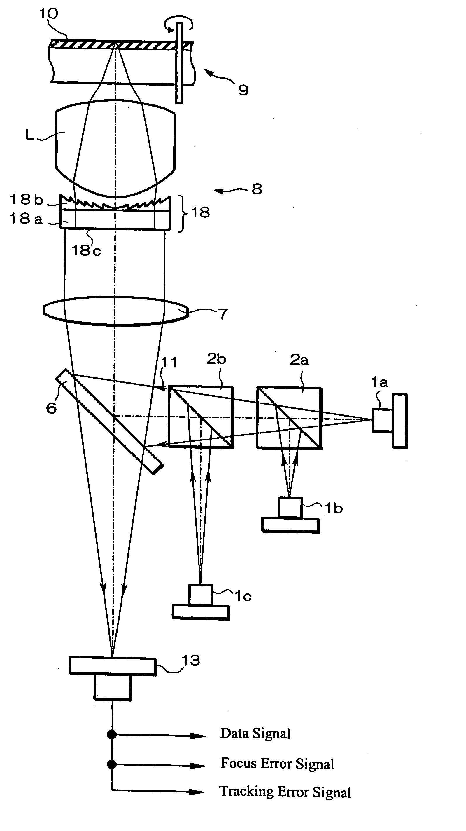
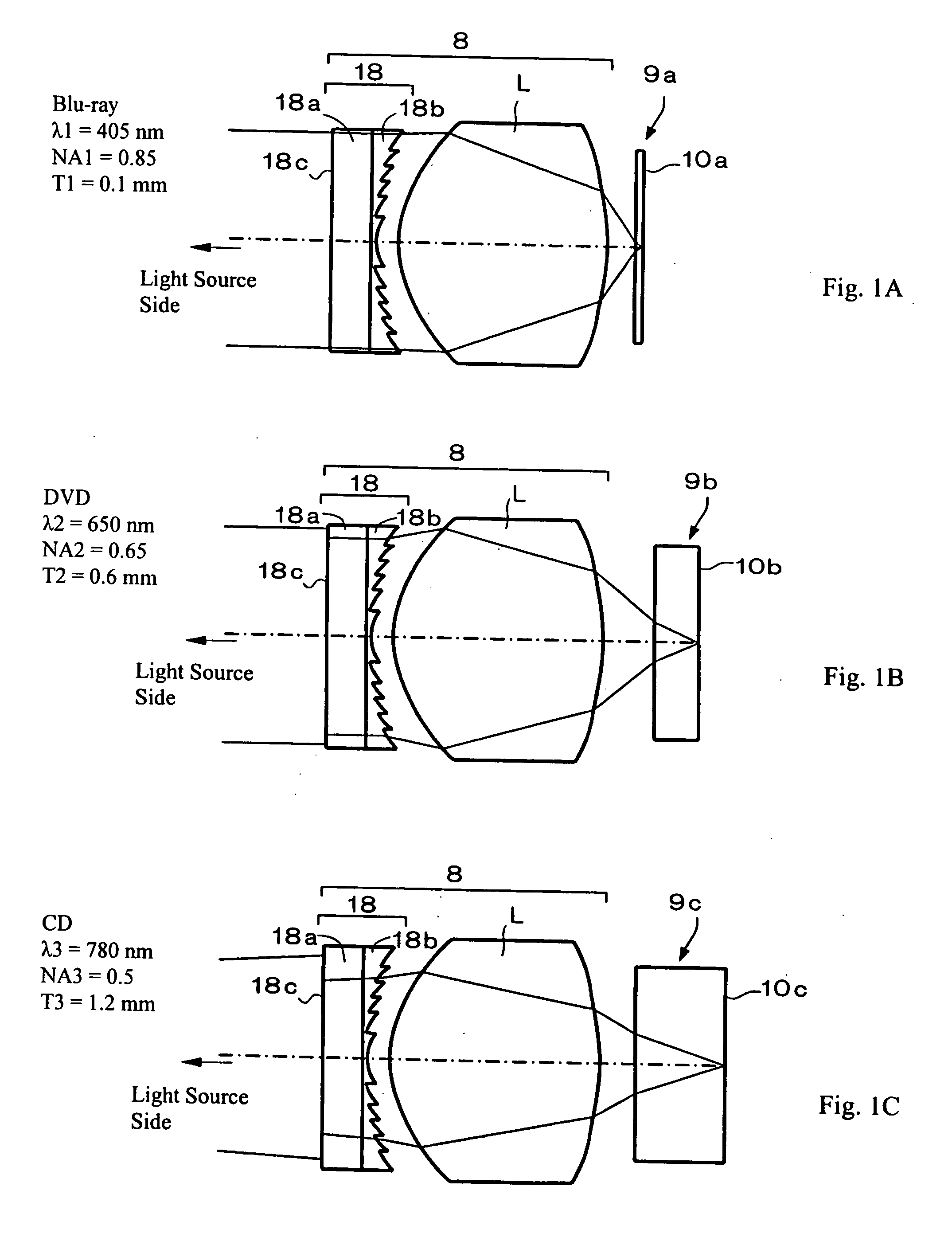
[0069]FIGS. 1A-1C are schematic diagrams that depict cross-sectional views of the objective optical system for optical recording media of Embodiment 1 of the present invention, with FIG. 1A showing the operation of the objective optical system when used with a first optical recording medium 9a, with FIG. 1B showing the operation of the objective optical system when used with a second optical recording medium 9b, and with FIG. 1C showing the operation of the objective optical system when used with a third optical recording medium 9c. As shown in FIGS. 1A-1C, the objective optical system of the present invention includes, in order from the light source side, an aperture control filter 18 with a diffractive optical function and an objective lens L. As shown in FIGS. 1A-1C, a constant distance is maintained between the aperture control filter 18 with a diffractive optical function and the objective lens L when different wavelengths and recording media are used. The aperture control filt...

embodiment 2

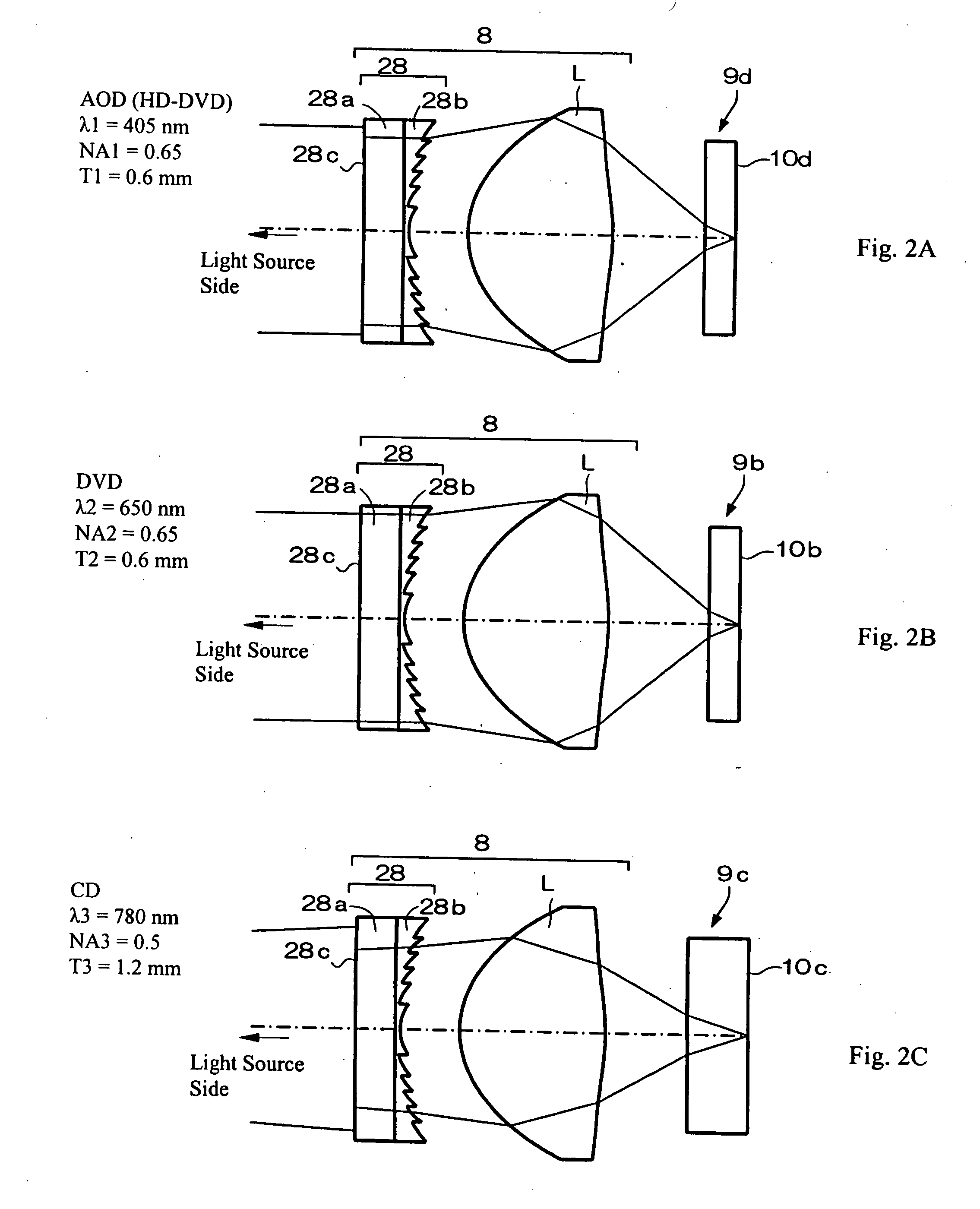
[0074]FIGS. 2A-2C are schematic diagrams that depict cross-sectional views of the objective optical system for optical recording media of Embodiment 2 of the present invention, with FIG. 2A showing the operation of the objective optical system when used with a first optical recording medium 9d, with FIG. 2B showing the operation of the objective optical system when used with a second optical recording medium 9b, and with FIG. 2C showing the operation of the objective optical system when used with a third optical recording medium 9c. As shown in FIGS. 2A-2C, the objective optical system of the present invention includes, in order from the light source side, an aperture control filter 28 with a diffractive optical function and an objective lens L. As shown in FIGS. 2A-2C, a constant distance is maintained between the aperture control filter 28 with a diffractive optical function and the objective lens L when different wavelengths and recording media are used. The aperture control filt...

embodiment 3

[0077]FIGS. 3A-3C are schematic diagrams that depict cross-sectional views of the objective optical system for optical recording media of Embodiment 3 of the present invention, with FIG. 3A showing the operation of the objective optical system when used with a first optical recording medium 9a, with FIG. 3B showing the operation of the objective optical system when used with a second optical recording medium 9b, and with FIG. 3C showing the operation of the objective optical system when used with a third optical recording medium 9c. As shown in FIGS. 3A-3C, the objective optical system of the present invention includes, in order from the light source side, an aperture control filter 38 with a diffractive optical function and an objective lens L. As shown in FIGS. 3A-3C, a constant distance is maintained between the aperture control filter 38 with a diffractive optical function and the objective lens L when different wavelengths and recording media are used. The aperture control filt...


PUM


Abstract

An objective optical system for focusing light from a light source onto optical recording media includes an aperture control filter with a diffractive optical function formed as a glass plate with an aperture control structure on one side and a diffractive optical structure, such as a plastic diffractive optical element adhered to the glass plate on the other side, and an objective lens. The objective optical system focuses three light beams of three different wavelengths at three different numerical apertures onto desired positions of three different recording media with substrates of different thicknesses, such as a BD (or an AOD), a DVD, and a CD, that introduce different amounts of spherical aberration in the focused beams. The objective optical system provides compensating spherical aberration to the three light beams while keeping constant the distance between the aperture control filter with a diffractive optical function and the objective lens.

Description

TECHNICAL FIELD OF THE INVENTION [0001] The present invention relates to an objective optical system for an optical recording medium that, when recording or reproducing information, efficiently focuses light of any one of three different wavelengths onto an appropriate corresponding recording medium according to standardized characteristics such as the numerical aperture of the objective optical system used, the wavelength of the light selected, and the substrate thickness of the optical recording medium. In addition, the present invention relates to an optical pickup device using such an objective optical system. More specifically, the present invention relates to an objective optical system for an optical recording medium wherein a diffractive optical element is used to diffract light in order to efficiently focus light of any one of the three wavelengths onto a corresponding one of the three optical recording media, and it also relates to an optical pickup device using such an ob...

Claims


Application Information

Patent Timeline
IPC IPC(8): G11B7/00
CPCG11B7/1275G11B7/1367G11B7/1374G11B7/1376G11B7/139G11B2007/0006
Inventor KITAHARA, YUKATSUMA, TOSHIAKIMORI, MASAOORI, TETSUYA
Owner FUJI PHOTO OPTICAL CO LTD
Why Eureka
Try Eureka