Telescopic tube assembly for a clothes rack

a technology of telescopic tube and clothes rack, which is applied in the direction of fastening means, rod connections, connections, etc., can solve the problems of uneven inner tube sliding movement relative to the outer tube, poor positioning effect between the inner tube and the outer tube, and uneven inner tube movement inside the outer tube, etc., to achieve the effect of convenient adjustment of the height of the clothes rack

Inactive Publication Date: 2006-04-13
WANG CHI CHUNG
View PDF7 Cites 3 Cited by
  • Summary
  • Abstract
  • Description
  • Claims
  • Application Information

AI Technical Summary

Benefits of technology

[0006] The primary objective of the present invention is to provide an improved telescopic tube assembly for a clothes rack. The telescopic tube assembly is able to enable the clothes rack user to easily adjust the clothes rack height.
[0007] A different objective of the present invention is that the telescopic tube assembly is able to provide a uniform friction force between the inner tube and the outer tube so that the movement of the inner tube relative to the outer tube is smooth.

Problems solved by technology

However, the positioning effect between the inner tube and the outer tube is not as good as expected.
Because the positioning force between the inner tube and the outer tube relies only on the friction force between the boss and the inner periphery of the outer tube, the inner tube's sliding movement relative to the outer tube may not be linear especially when the boss is not fully disengaged with the inner periphery of the outer tube.
That is, the inner tube's movement inside the outer tube may not be smooth due to the possible inclination of the inner tube relative to the outer tube.

Method used


Image

  • Telescopic tube assembly for a clothes rack
  • Telescopic tube assembly for a clothes rack
  • Telescopic tube assembly for a clothes rack

Examples


Embodiment Construction

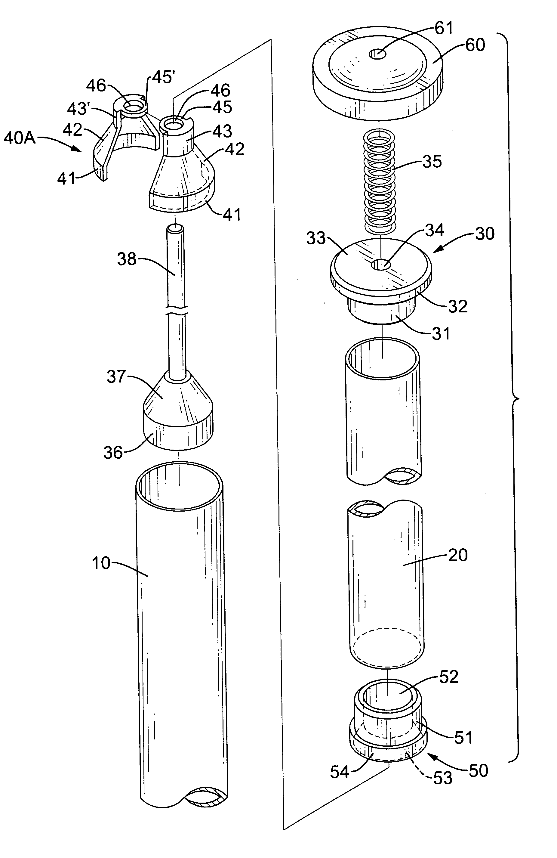
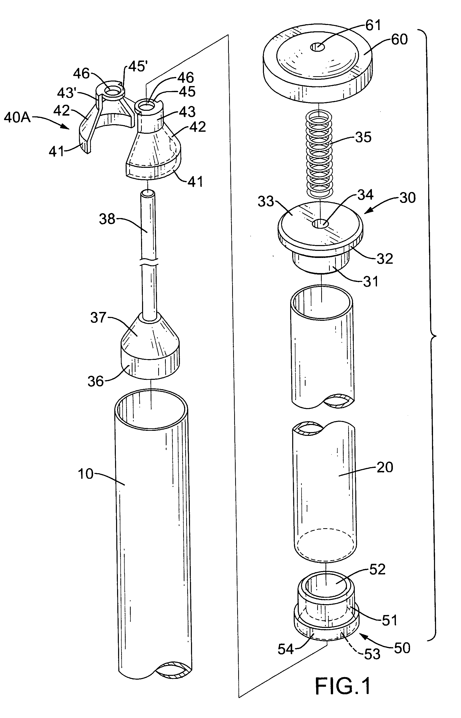
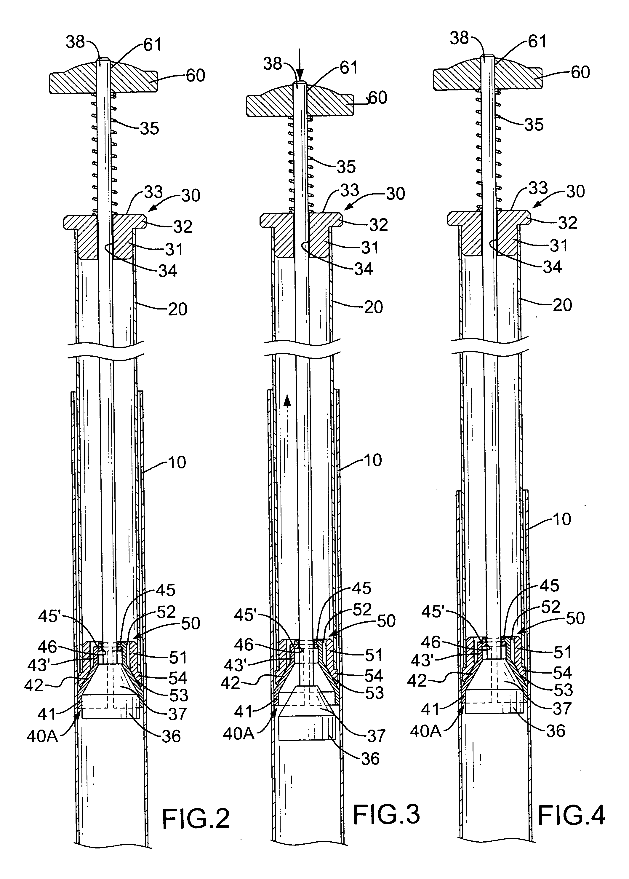
[0015] With reference to FIGS. 1 and 2, the telescopic tube assembly in accordance with the present invention includes an outer tube (10) with a top open end and an inner tube (20) slidably received inside the outer tube (10) and having two open ends.

[0016] A top cap (30) is provided to close the top open end of the inner tube (20) and has an annular skirt (31) integrally extending from a circular disk (33), a first flange (32) formed on an outer peripheral edge of the circular disk (33) and a first through hole (34) centrally defined through the circular disk (33).

[0017] A bottom cap (50) is provided to close the bottom open end of the inner tube (20) and has a tubular extension (51), a second through hole (52) defined through the tubular extension (51) to correspond to and align with the first through hole (34) of the top cap (30), a first conical abutting face (53) formed on a bottom inner face of the tubular extension (51) and a second flange (54) formed on an outer peripheral...


PUM


Abstract

A telescopic tube assembly includes an outer tube, an inner tube slidably received in the outer tube, an abutting device provided under the bottom cap and having a first flange, a first conical abutting face formed on top of the first flange, a hollow cylinder formed on top of the first conical abutting face and a first through hole defined through the hollow cylinder, and a drive rod extending into a second through hole in a stop. The drive rod has a second conical abutting selectively engaged with the first conical abutting face of the abutting device such that movement of the stop is able to selectively expand the first conical abutting face to allow the first flange to abut the inner periphery of the outer tube to position the inner tube relative to the outer tube.

Description

BACKGROUND OF THE INVENTION [0001] 1. Field of the Invention [0002] The present invention relates to a telescopic tube assembly, and more particularly to a telescopic tube assembly for a clothes rack to enable the clothes rack user to easily adjust the height of the clothes rack. [0003] 2. Description of Related Art [0004] A conventional clothes rack has two telescopic tube assemblies, and a crossbar respectively and securely connected to proximal ends of the two telescopic tube assemblies. Each telescopic tube assembly has an inner tube and an outer tube having the inner tube slidably received inside the outer tube via a positioning device which is mounted around the inner tube. The positioning device for positioning the inner tube inside the outer tube may be a boss eccentrically formed on an outer periphery of the inner tube to abut an inner periphery of the outer tube such that when the boss abuts the inner periphery of the outer tube, the inner tube is positioned relative to th...

Claims


Application Information

Patent Timeline
Patent Type & Authority Applications(United States)
IPC IPC(8): F16B7/10
CPCY10T403/32467F16B7/149
Inventor WANG, CHI-CHUNG
Owner WANG CHI CHUNG
Why Eureka
Try Eureka