Blower capable of reducing secondary flow

Inactive Publication Date: 2006-04-13
ASIA TAL COMPONENT
View PDF7 Cites 3 Cited by
  • Summary
  • Abstract
  • Description
  • Claims
  • Application Information

AI Technical Summary

Benefits of technology

[0007] An object of the present invention is to pr

Problems solved by technology

The secondary flow can result in loud noise and block the airflow

Method used


Image

  • Blower capable of reducing secondary flow
  • Blower capable of reducing secondary flow
  • Blower capable of reducing secondary flow

Examples


Embodiment Construction

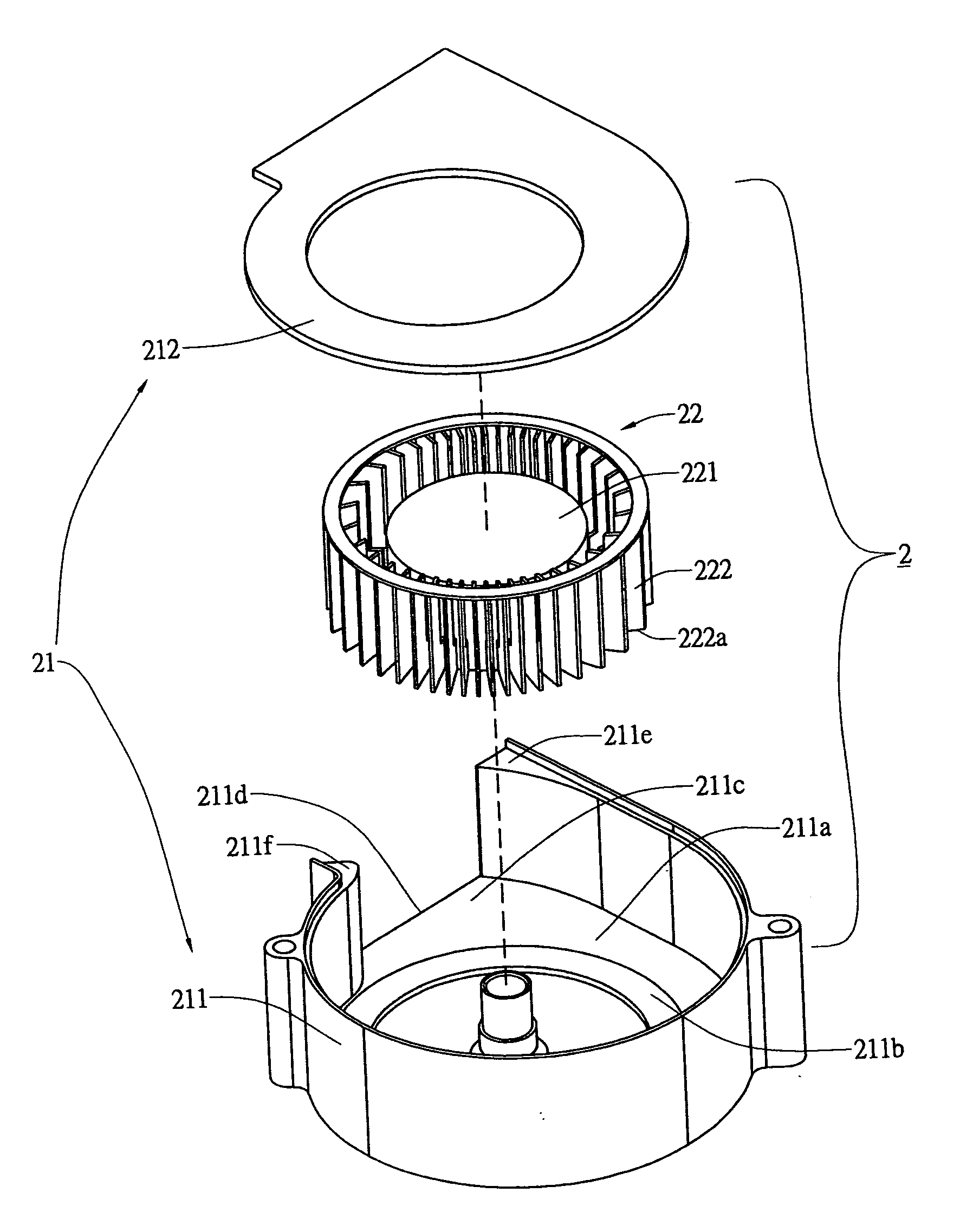
[0015] Referring to FIGS. 4 and 5, a blower 2 according to the present invention comprises a frame 21 and a wheel blade part 22. The wheel blade part 22 is composed of a hub 221 and a plurality of blades 222 surrounded the hub 221. The frame 21 is composed of a base 211 and an lid plate 212 and base 211 at the inner side 211a thereof is provided with a projection part 211b corresponding to the lower edges 222a of the blades 222 on the wheel blade part 22.

[0016] Referring to FIG. 6, the projection part 211b reduces the distance between the lower edges 222a and the inner side 211a to the least extent and partitions the distance. When the wheel blade part 22 rotates, the airflow introduced by the blades 222 can be restricted by the projecting part 211b to allow the airflow being not easy to constitute secondary flow between the lower edges 222a of the blades 222 and the inner side 211a of the base 211.

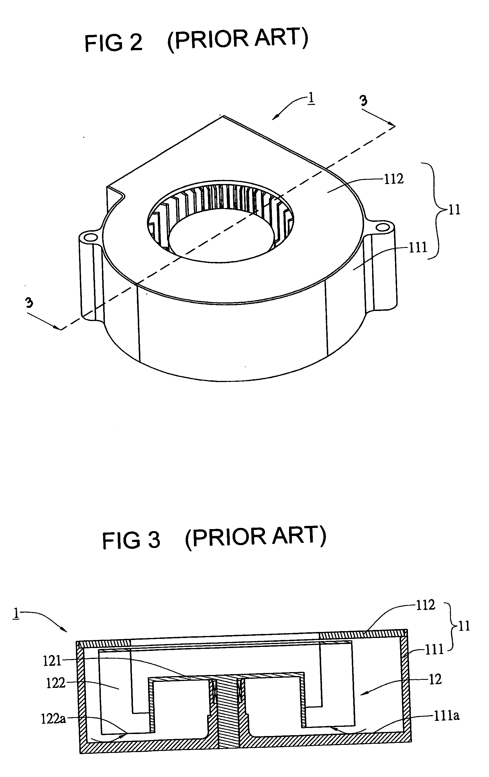
[0017] Referring to FIGS. 3 to 6, the projection part 211b at the inner side of the...


PUM


Abstract

A blower capable of reducing secondary flow comprises a frame and a wheel blade part. The wheel blade part is mounted in the frame. The wheel blade part is composed of a hub and a plurality of blades surrounding the hub. The frame is composed of a base and an upper lid plate with a projection part being provided at inner side of the base. The projection part corresponds to the blades on the wheel blade part. A first guide part and a second guide part are provided at an air passage of the base near an opening thereof. The secondary flow produced in the blower can be reduced by way of the projection at the inner side of the base and the first and second guide parts at the air passage of the base near the opening thereof.

Description

BACKGROUND OF THE INVENTION [0001] 1. Field of the Invention [0002] The present invention is related to a blower capable of reducing secondary flow and particularly to a frame device used in a blower. [0003] 2. Brief Description of the Related Art [0004] Referring to FIGS. 1 and 2, the conventional blower 1 includes a frame 11 and a wheel blade part 12 disposed in the frame 11. The frame 11 is composed of a base 111 and an upper lid plate 112. The wheel blade part 12 is composed of a hub 121 and a plurality of blades 122 surrounding the hub 121. [0005] Referring to FIG. 3, a distance results between the lower edges 122a of the blade 122 and the inner side 111a of the base 111 to produce a secondary flow at a space formed by the distance. The secondary flow can result in loud noise and block the airflow so as to reduce the overall air pressure and amount of the airflow. [0006] Although the base 111 of the conventional blower 1 can be lifted the inner side 111a thereof to decrease the...

Claims


Application Information

Patent Timeline
IPC IPC(8): F04D29/44
CPCF04D29/162F04D29/4226
Inventor WANG, CHUNG-SHU
Owner ASIA TAL COMPONENT
Why Eureka
Try Eureka