Connector transfer tool for internal structure stabilization systems

Inactive Publication Date: 2006-04-13
THEKEN SPINE
View PDF99 Cites 349 Cited by
  • Summary
  • Abstract
  • Description
  • Claims
  • Application Information

AI Technical Summary

Problems solved by technology

Over time, or because of accidents, the intervertebral discs loose height, become cracked, dehydrated, or herniated.
The result is that the disc height is reduced leading to compression

Method used


Image

  • Connector transfer tool for internal structure stabilization systems
  • Connector transfer tool for internal structure stabilization systems
  • Connector transfer tool for internal structure stabilization systems

Examples


Embodiment Construction

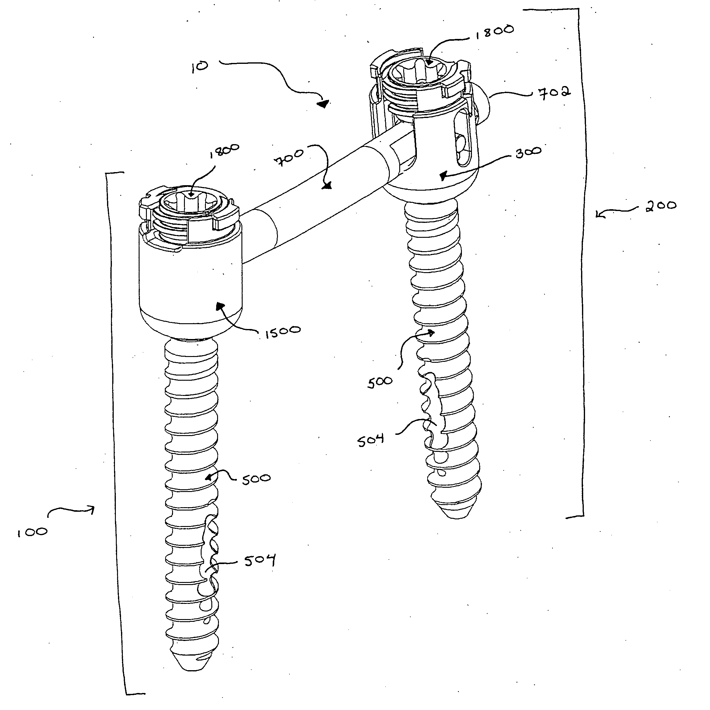
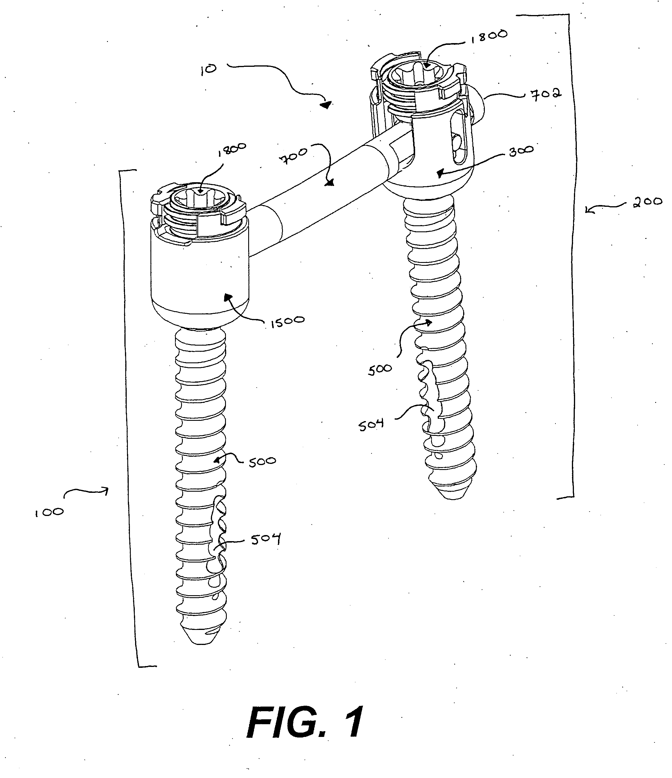
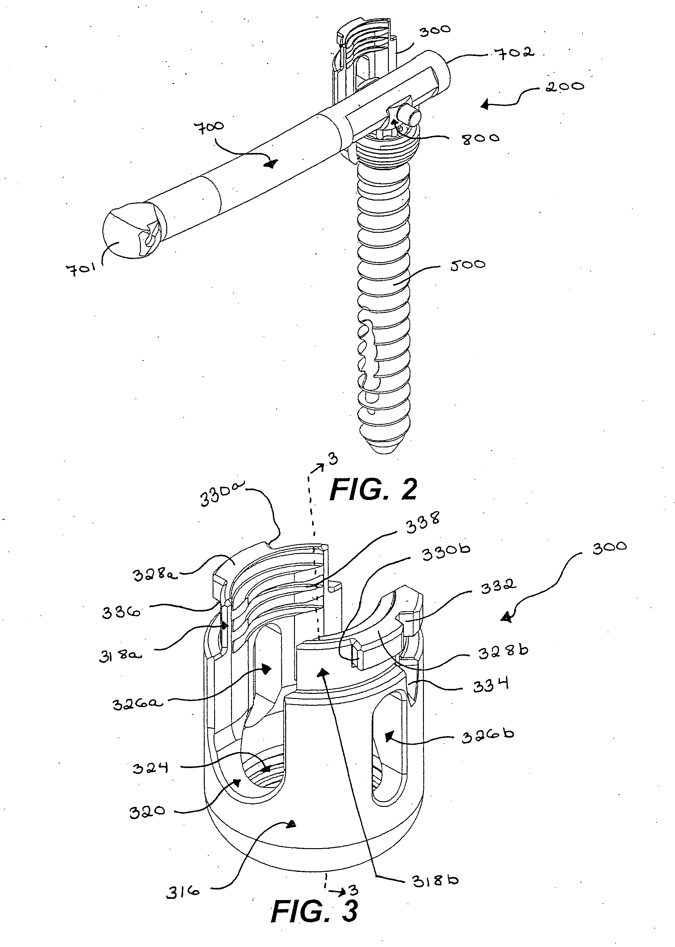
[0095] To better understand the devices, assemblies, tools, and methods described below, and understanding of the procedure through which the back stabilization of the present invention is placed into the vertebrae of a patient is required. Reference is made to the figure numbers where specific embodiments of the devices, assemblies, tools and methods are described in greater detail to aid in the understanding of those particular items.

[0096] An operation to insert a pedicle screw assembly into a patient's back to immobilize certain vertebrae in order to allow bone grafts to ultimately fuse those vertebrae begins with the surgeon inserting a standard bone biopsy needle into the pedicle of a first vertebra and using the bone biopsy needle to place a guide wire where the first pedicle screw should be inserted. Using the guide wire, progressively larger tissue expanders are inserted into the patient to expand, or dilate, the incision to the size necessary to accommodate the instrument...


PUM


Abstract

A tool is described for use in a stabilization system for bony structures such as vertebrae, where the system involves connected a connector from one bone anchor in a vertebra to a second bone anchor in another vertebra. The tool includes a handle attached to an arm. The arm is connected by a pivot to a connector engagement mechanism, the pivot allowing the connector engagement mechanism to move from an orientation inline with the arm to an orientation at an angle relative to the arm by rotating at the pivot. The connector engagement mechanism is engaged to an end of the connector when the tool is in its inline orientation and by causing the movement, which can be by the movement of a lever on the handle, of the connector engagement mechanism to the angled orientation, the end of the connector is moved into a position for engagement with the second bone anchor.

Description

CROSS-REFERENCE TO RELATED APPLICATIONS [0001] This application is a Utility Patent Application from Provisional Patent Application No. 60 / 617,461, filed Oct. 8, 2004 entitled “MEDICAL DEVICES AND METHODS FOR USE IN A MINIMALLY INVASIVE SPINAL FIXATION SYSTEM,” the disclosure of which is hereby incorporated herein by reference.TECHNICAL FIELD [0002] This invention relates to bone stabilization systems, and more particularly to tools for percutaneously rotating a connector to span two pedicle screw stabilization anchors. BACKGROUND OF THE INVENTION [0003] The human spine provides a vast array of functions, many of which are mechanical in nature. The spine is constructed to allow nerves from the brain to pass to various portions of the middle and lower body. These nerves, typically called the spinal cord, are located in a region within the spine called the spinal canal. Various nerve bundles emerge from the spine at different locations along the lateral length of the spine. In a healt...

Claims


Application Information

Patent Timeline
IPC IPC(8): A61F2/30A61B17/70A61B17/88
CPCA61B5/103A61B5/107A61B5/4504A61B17/1604A61B17/1655A61B17/1757A61B17/320016A61B17/3417A61B17/3421A61B17/3468A61B17/7002A61B17/7005A61B17/701A61B17/7011A61B17/7032A61B17/7037A61B17/7038A61B17/704A61B17/7082A61B17/7085A61B2017/320044A61B2019/461A61B2019/467A61B5/6878A61B5/6882A61B2090/061A61B2090/067
Inventor COLLERAN, DENNISSPITLER, JAMESROGERS, CAROLYN
Owner THEKEN SPINE
Why Eureka
Try Eureka