Electronic apparatus and optical pickup head tilting angle adjusting mechanism thereof

a technology of optical pickup and tilting angle, which is applied in the direction of disposing/mounting heads, instruments, data recording, etc., can solve the problems of inability to quantitate adjusting operation, the error rate is larger, and the reading may fail in a serious condition, so as to reduce human error and enhance the accuracy of the height of the guide rod.

Inactive Publication Date: 2006-04-13
PEGATRON
View PDF8 Cites 5 Cited by
  • Summary
  • Abstract
  • Description
  • Claims
  • Application Information

AI Technical Summary

Benefits of technology

[0013] As mentioned above, the electronic apparatus of the invention and the optical pickup head tilting angle adjusting mechanism thereof have the first guide rod or second guide rod disposed on the adjusting member, wherein the distance between the periphery of the supporting part and the rotating shaft is substantially gradually changed. Thus, the operator can adjust the height of the first guide rod or the second guide rod with respect to the base by rotating the adjusting member such that the light ray outputted from the optical pickup head is perpendicular to the surface of the optical disk. Compared to the prior art, the periphery of the adjusting member or the gear coaxial with the adjusting member has sawteeth in the electronic apparatus of the invention and the optical pickup head tilting angle adjusting mechanism thereof. Thus, the operator can quantitate the height adjusting level of the guide rod by rotating the gear in a predetermined number of sawteeth. Furthermore, because the height adjusting level of the guide rod may be quantitated, the operator's adjusting speed may be increased, and the precision of the height of the guide rod may be enhanced. In addition, the reproducibility of the adjusting member is high, and the human error may be reduced.

Problems solved by technology

The error rate gets larger as the jitter becomes larger, or even the reading may fail in a serious condition.
Consequently, the adjusting operation cannot be quantitated, and the reproducibility of the rotated screw 16 is not good such that the precision cannot be easily controlled, and the operator has to repeatedly adjust the screw.
When automatic adjusting processes are to be performed, the feedback signals also have to be repeatedly identified, and a lot of time is thus wasted.

Method used


Image

  • Electronic apparatus and optical pickup head tilting angle adjusting mechanism thereof
  • Electronic apparatus and optical pickup head tilting angle adjusting mechanism thereof
  • Electronic apparatus and optical pickup head tilting angle adjusting mechanism thereof

Examples


Embodiment Construction

[0021] The present invention will be apparent from the following detailed description, which proceeds with reference to the accompanying drawings, wherein the same references relate to the same elements.

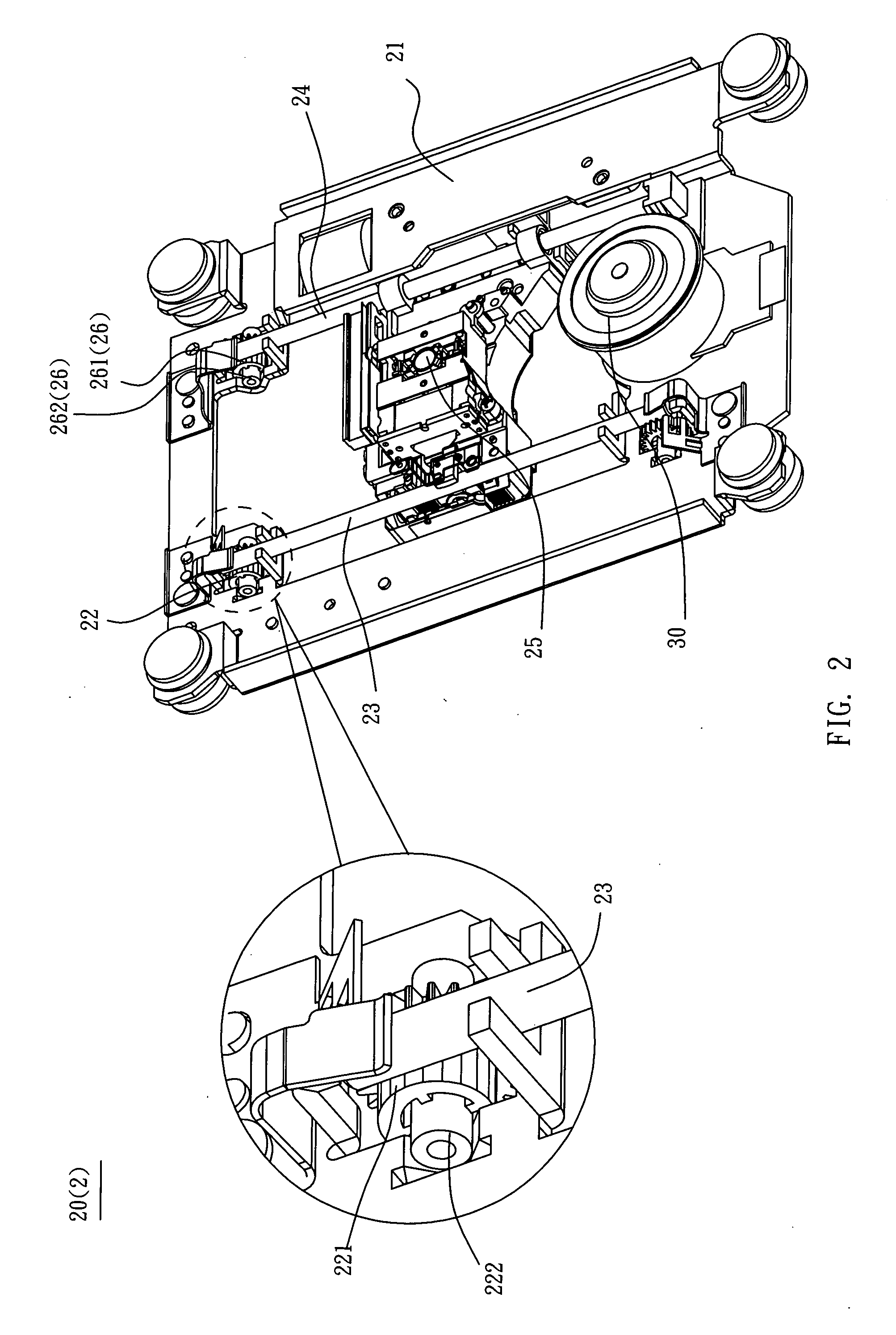
[0022] First, an electronic apparatus according to a preferred embodiment of the invention will be described with reference to FIGS. 2 to 4.

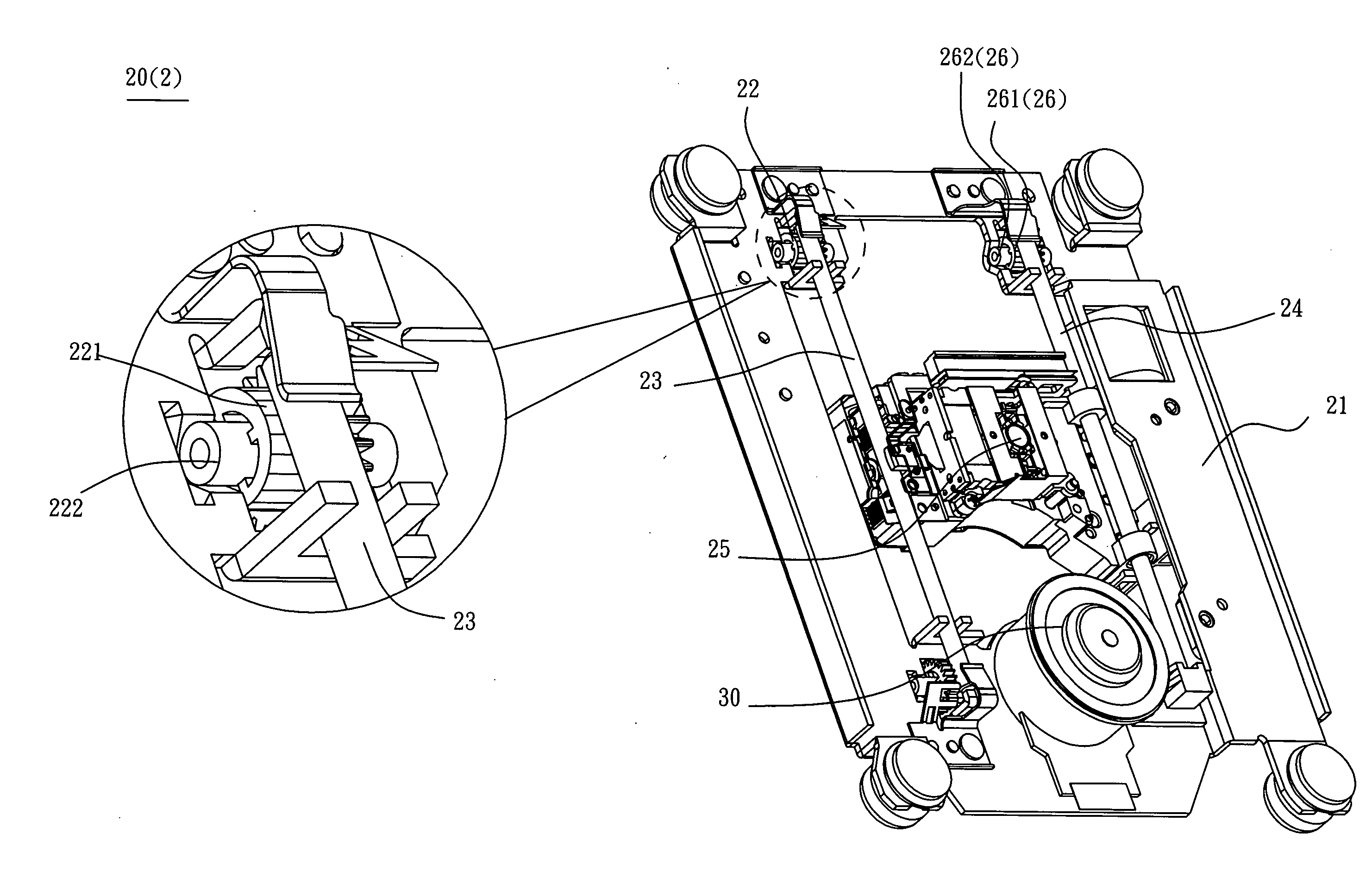
[0023] With reference to FIG. 2, an electronic apparatus 2 includes a base 21, a first adjusting member 22, a first guide rod 23, a second guide rod 24, and an optical pickup head 25. In this embodiment, the electronic apparatus 2 is an optical disk drive as an example.

[0024] As shown in FIG. 2, the first adjusting member 22 has a first supporting part 221 and a first rotating shaft 222. The first adjusting member 22 is pivoted to the base 21 by the first rotating shaft 222. In this embodiment, the electronic apparatus 2 having two first adjusting members 22 serves an example, and the first adjusting members 22 are respectively disposed at two...


PUM

PropertyMeasurementUnit
tilting angleaaaaaaaaaa
distanceaaaaaaaaaa
axial movementaaaaaaaaaa

Abstract

An electronic apparatus includes a base, a first adjusting member, a first guide rod, a second guide rod, and an optical pickup head. The first adjusting member has a first supporting part, and a first rotating axis. The first rotating axis is passed through the first supporting part. The distance between the periphery of the first supporting part and the first rotating axis gradually changes. The first adjusting member is pivoted to the base by the first rotating axis. At least one part of the first guide rod is disposed on the periphery of the first supporting part. At least one part of the second guide rod connects with the base. The optical pickup head is disposed both on the first guide rod and the second guide rod. An optical head tilting angle adjusting mechanism is provided in the electronic apparatus.

Description

BACKGROUND OF THE INVENTION [0001] 1. Field of Invention [0002] The invention relates to an electronic apparatus and an optical pickup head adjusting mechanism thereof, and more particularly to an electronic apparatus with an optical pickup head and a tilting angle adjusting mechanism of the optical pickup head of the electronic apparatus. [0003] 2. Related Art [0004] Recently, using an optical disk to record voices, images and personal file data has become the popular data storage method. With the large storage space of the optical disk and the property of the optical disk that is easily preserved, people can exchange information rapidly and get a lot of fun using the optical disk. The optical disk drive serving as a device for reading the optical disk has further become one of the indispensable products in the present computer peripheral apparatus. [0005] In general, when the optical disk drive is reading data on the optical disk, the jitter of the radio frequency (RF) signal tran...

Claims


Application Information

Patent Timeline
Patent Type & Authority Applications(United States)
IPC IPC(8): G11B7/08
CPCG11B7/082G11B7/08582
Inventor WU, TSUNG-LIN
Owner PEGATRON
Why Eureka
Try Eureka