

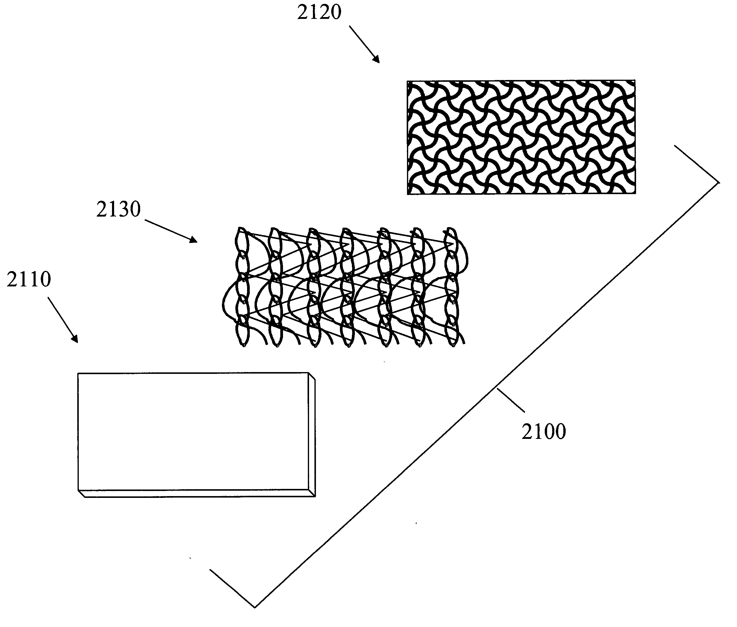
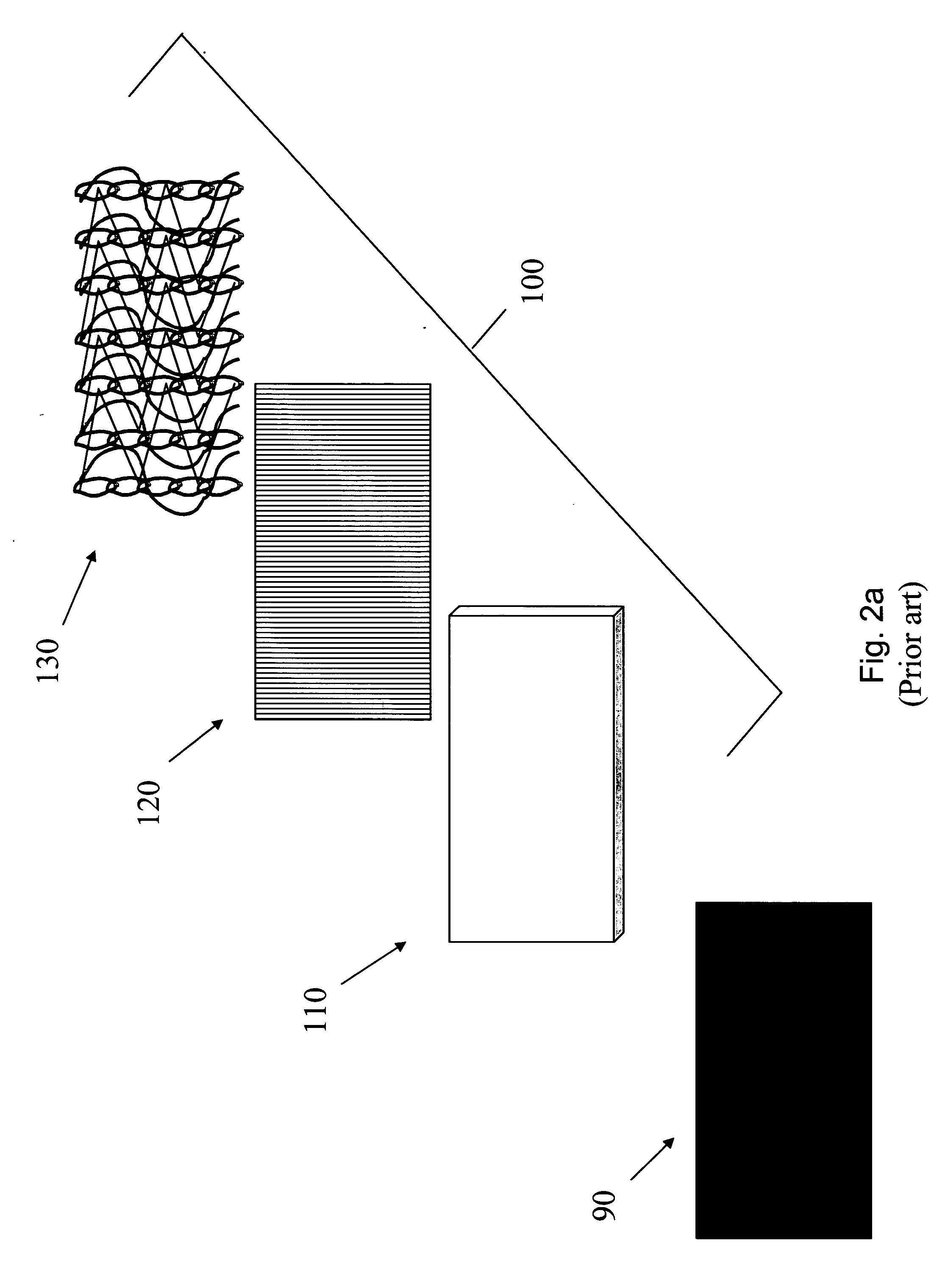
Bonding patterns for construction of a knitted fabric landing zone
a knitting fabric and landing zone technology, applied in knitting, snap fasteners, ornamental textile articles, etc., can solve the problems of not being able to construct the optimal fastening system, the loops will no longer be free for subsequent fastening to the hooks, and the risk of potentially gluing down the loops within the area of the chain
- Summary
- Abstract
- Description
- Claims
- Application Information
AI Technical Summary
Benefits of technology
Problems solved by technology
Method used
Image

Examples
Embodiment Construction
Definitions:
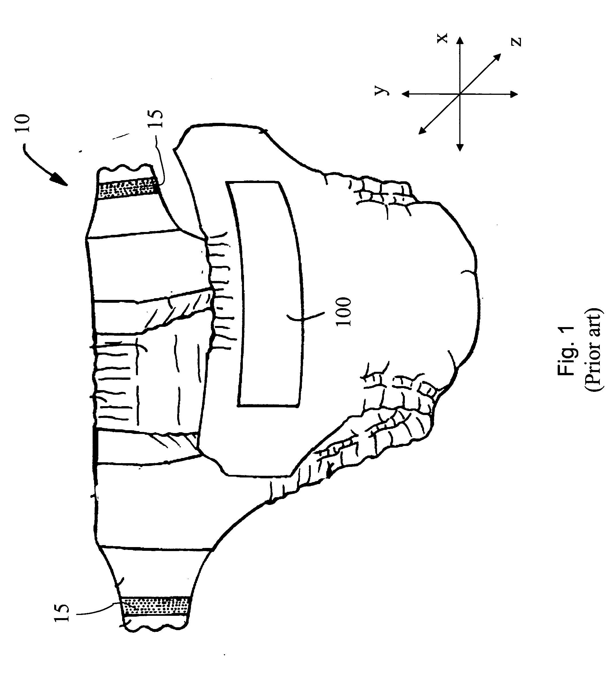
[0069] The term “absorbent article” herein refers to devices which absorb and contain body exudates and, more specifically, refers to devices which are placed against or in proximity to the body of the wearer to absorb and contain the various exudates discharged from the body, such as: incontinence briefs, incontinence undergarments, absorbent inserts, diaper holders and liners, feminine hygiene garments and the like.
[0070] The term “disposable” is used herein to describe absorbent articles which generally are not intended to be laundered or otherwise restored or reused as absorbent articles (i.e., they are intended to be discarded after a single use and, preferably, to be recycled, composted or otherwise discarded in an environmentally compatible manner).
[0071] The term “diaper” herein refers to an absorbent article generally worn by infants and incontinent persons about the lower torso.
[0072] The term “pant”, as used herein, refers to disposable garments having a ...
PUM
 Abstract
Description
Claims
Application Information