Fixed-blade knife with pivotable side pieces

a fixed-blade knife and side piece technology, which is applied in the field of fixed-blade knives with pivotable side pieces, can solve the problems of not being able to store knives, not being able to damage leather and other flexible sheath materials, and not being able to increase etc., to achieve convenient use, not increasing the size and profile of fixed-blade knives, and being easy to loca

Inactive Publication Date: 2006-04-20
BUCK KNIVES
View PDF24 Cites 29 Cited by
  • Summary
  • Abstract
  • Description
  • Claims
  • Application Information

AI Technical Summary

Benefits of technology

[0008] The present invention provides a fixed-blade knife with an integral side-piece structure that may serve as either part of the handle or as a cover that protects the blade in storage. The side pieces may be made sufficiently large so that the integral blade is recessed well within the boundaries of the side pieces when the side pieces are pivoted to their closed position, protecting the edge of the blade from external contacts that would either damage the edge or cause the edge to injury someone. A locking mechanism retains the side pieces in a desired position, such as a fully open or fully closed position. A preferred form of the locking mechanism automatically releasably locks the side pieces into the desired positions, when those blade positions are reached during rotation of the side pieces. It may also be made to releasably lock the folding blade into other positions, such as half open. The preferred locking release is conveniently located on the side of the fixed-blade knife and can be readily located by the fingers of the user of the fixed-blade knife. The approach produces a strong, positive lock that is stronger than a liner lock and whose mechanism does not increase the size and profile of the fixed-blade knife. The lock is stable, so that there is no looseness of the blade in the locked position. The lock is easy to use, and opening and unlocking can be accomplished with one hand.
[0011] Optionally, a limit structure prevents overrotation of the side pieces past a position corresponding to the alignment of the locking button with the enlarged locking-slot bore. The preferred form of the limit structure includes a limit pin extending on each side of the blade, and a limit slot in at least one, and preferably each, of the side pieces. The limit slot comprises a limit-slot angular segment of constant radius centered on the blade pivot bore. The limit pin of the blade engages the limit slot, and the angular length of the limit slot determines the permitted angular rotation of the blade. Typically, the permitted angular rotation of the blade coincides with the position or positions of the enlarged locking-slot bores. The limit structure is desirably present to provide a reaction force against the force of the locking wedge against the side of the enlarged locking-slot bore when the blade is locked, so that there is a secure lock without mechanical play.
[0013] The presence of the tang distinguishes the present fixed-blade knife from conventional folding-blade knives. In the present case, the tang, which is integral with the implement, transfers the working force applied through the implement into the hand of the user of the knife, through the side pieces if they are rotated to the open position to overlie the tang, or directly if the side pieces are rotated out of the way. The working force is thus distributed over a relatively large area. In a conventional folding knife, the working force applied when the implement is open is transferred through the pivot mechanism of the folding blade and thence to the handle. This pivot mechanism is a weak link in the chain of force application. The locking mechanism for the side pieces of the present approach reacts any force seeking to unlock the implement from its locked position through the thickness of the material that constitutes the unitary blade, rather than through relatively thin or narrow notches, edges, and similar locking contact surfaces that are usually employed in the locks of folding knifes. Thus, both the primary working-force reaction and the locking force of the side pieces are substantially stronger than those found in conventional folding-blade knives.

Problems solved by technology

Because the sharp blade of a knife potentially can cause injury or damage when the knife is not intentionally in use, provision must be made to store the knife safely.
The sheath is a separate piece from the fixed-blade knife, and there is always the possibility that it will not be available for storage of the knife, as for example if the sheath is lost.
Additionally, it is possible to damage leather and other flexible sheath materials with the cutting edge of the blade, particularly when the blade is inserted into the sheath.
However, it may be inconvenient to store the knife in an externally carried sheath, due both to size and visual considerations.

Method used


Image

  • Fixed-blade knife with pivotable side pieces
  • Fixed-blade knife with pivotable side pieces
  • Fixed-blade knife with pivotable side pieces

Examples


Embodiment Construction

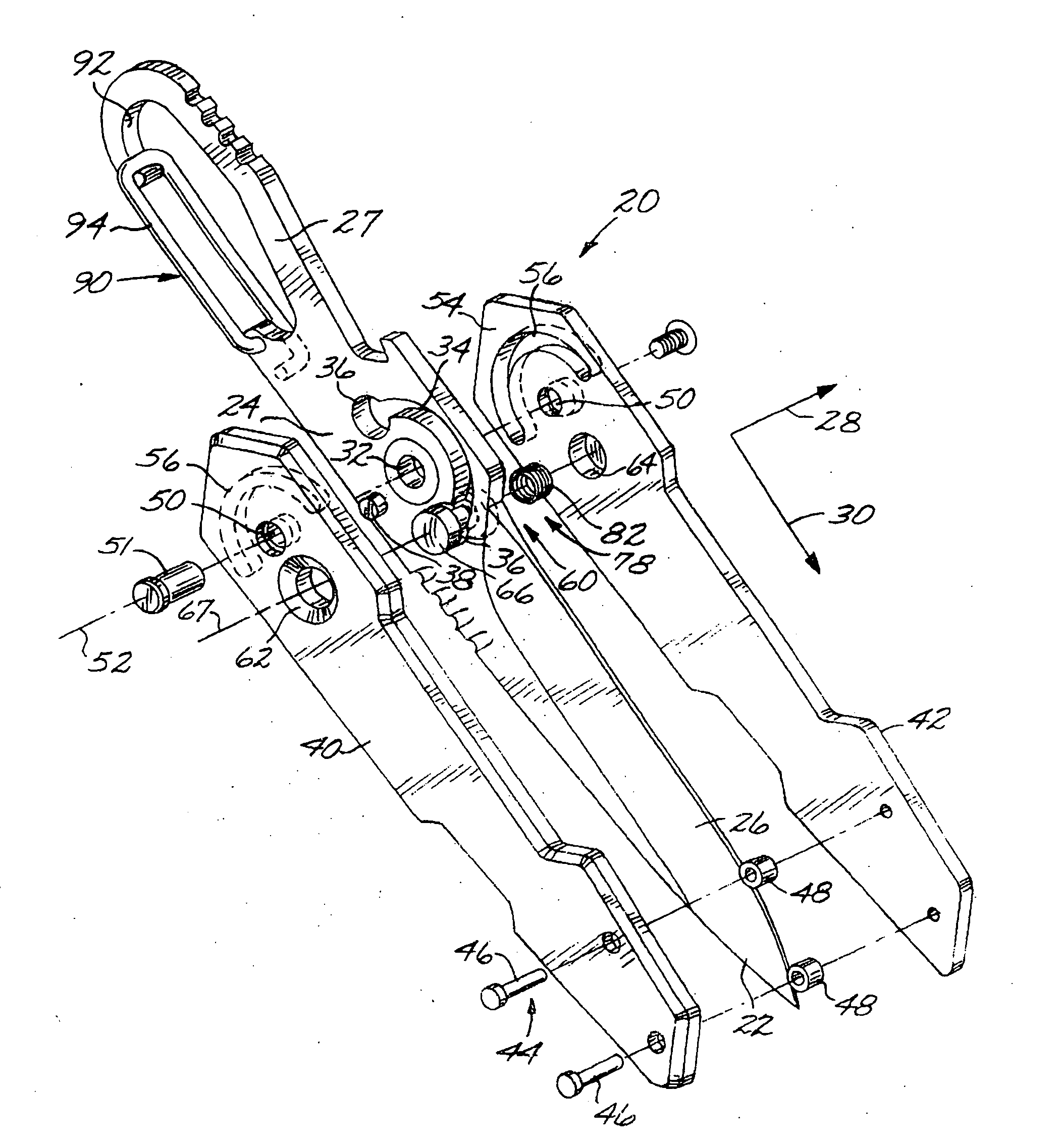
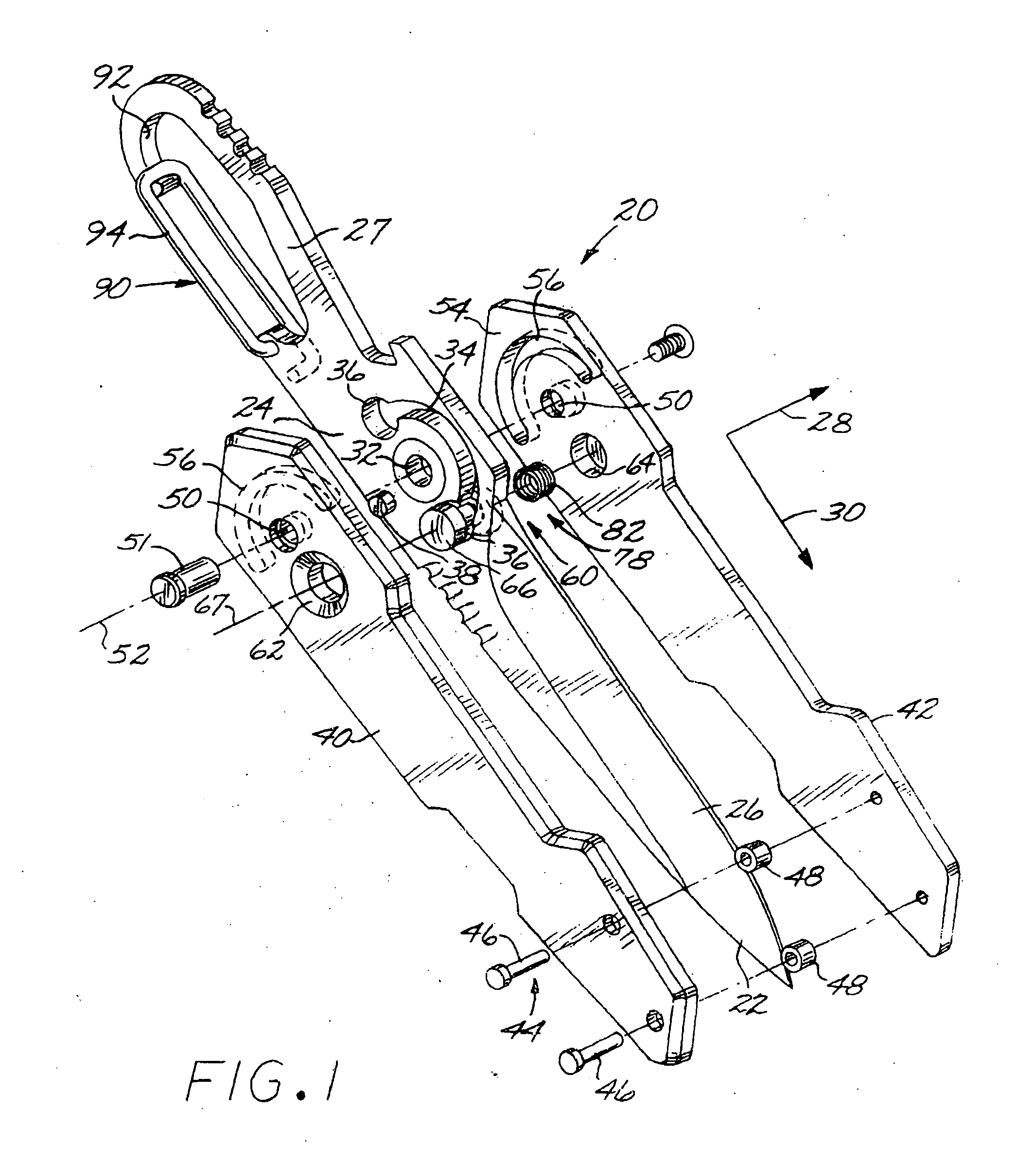
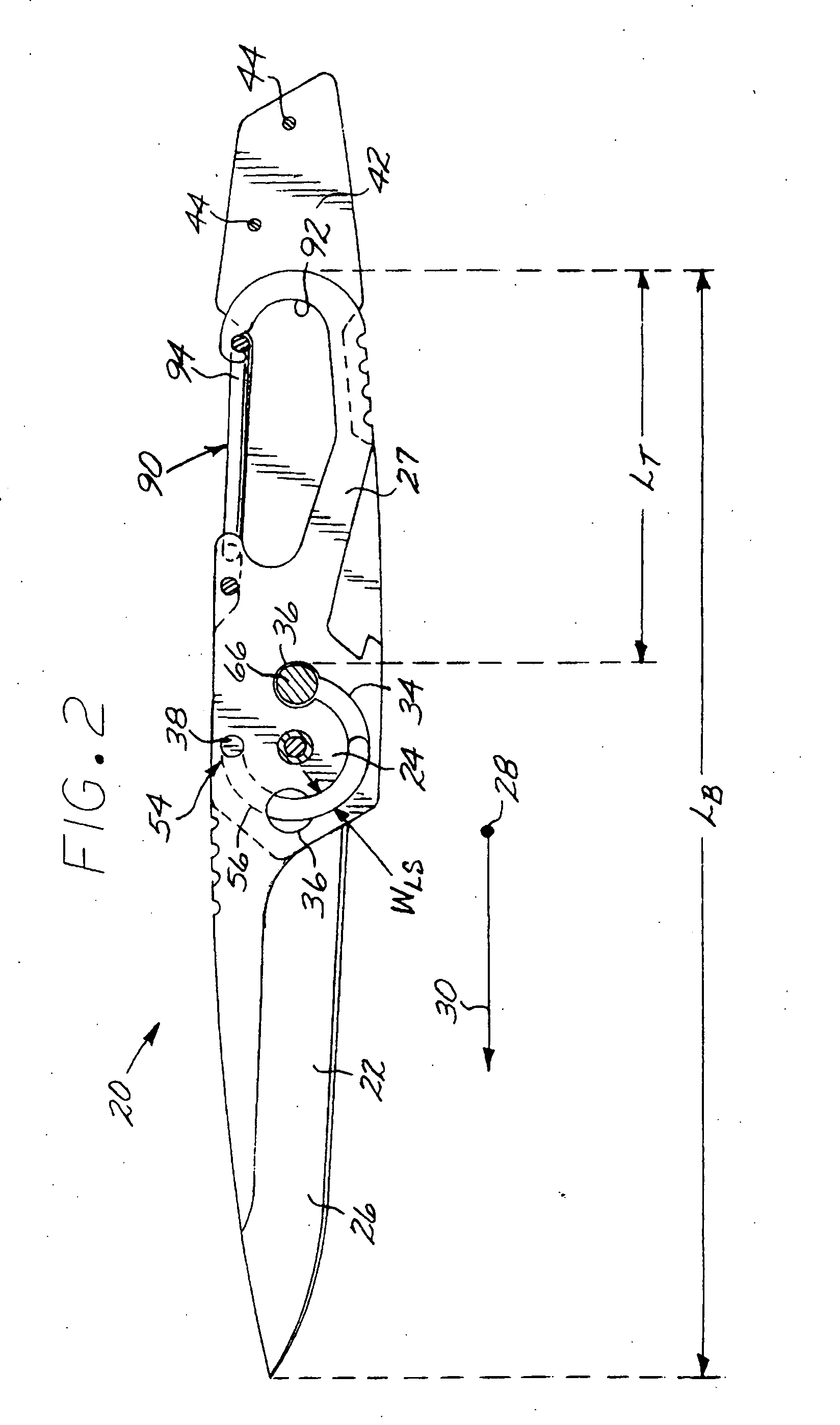
[0021]FIGS. 1-2 depict a fixed-blade knife 20 that includes a unitary blade 22 having a pivot region 24, an implement 26 extending in one direction from the pivot region 24, and a tang 27 extending in the opposite direction from the pivot region 24. That is, the pivot region 24 lies between the implement 26 and the tang 27. As used herein, a “blade” is any article that is generally thin in a first dimension 28 and longer in a second dimension 30 (also termed the “direction of elongation” of the unitary blade 22) that is perpendicular to the first dimension 28. The thin dimension 28 lies perpendicular to a “blade plane”, which is the plane of the illustration in FIG. 2, and the direction of elongation 30 lines in the blade plane. As used herein, “unitary blade” refers to a blade made of a single piece of material. In this case, the entire unitary blade, including the implement 26, the pivot region 24, and the tang 27 are all made of the same piece of material, typically a metal such ...


PUM


Abstract

A fixed-blade knife includes a unitary blade having an implement, a tang, and a pivot region between the implement and the tang. The unitary blade is disposed between a pair of parallel and spaced-apart side pieces that pivot to cover or expose the implement. In the pivoted position wherein the implement is exposed, the side pieces form part of the handle that is used to grasp the knife. A locking structure locks the side pieces in a selectable position, and a limit structure prevents overrotation of the side pieces.

Description

[0001] This application is a continuation-in-part of application Ser. No. 09 / 758,915, filed Jan. 10, 2001, for which priority is claimed and whose disclosure is incorporated by reference. [0002] This invention relates to a fixed-blade knife and, more particularly, to such a knife with pivotable side pieces and limiting and locking structures that limit the pivoting of the side pieces and controllably lock the side pieces in relation to the blade.BACKGROUND OF THE INVENTION [0003] Knives may be generally classified as fixed-blade and folding-blade types. The common hunting knife and folding pocket knife are examples. The fixed-blade knife includes a backbone structure that defines an implement such as a blade with a cutting edge, and a tang to which the sides of the handle are affixed. The folding-blade knife typically joins the implement to the handle with a pivot structure. Because the sharp blade of a knife potentially can cause injury or damage when the knife is not intentionally...

Claims


Application Information

Patent Timeline
Patent Type & Authority Applications(United States)
IPC IPC(8): B26B3/06B26B11/00
CPCB26B1/046B26B3/06B26B11/00B25F1/006B25F1/04
Inventor HATCHER, BRANDONHULL, STEPHEN J.HUSSEY, DEANLINN, ERIC P.PINTO, ROBERT L.WILLIAMS, MICHAEL E.HLAVAC, MATHEW
Owner BUCK KNIVES
Why Eureka
Try Eureka