Assembled block

a technology of assembled blocks and blocks, applied in the field of three-dimensional blocks, can solve the problems of increasing manufacturing costs, severely restricting the final shape of assembled blocks,

Inactive Publication Date: 2006-04-20
YOSHIRITSU
View PDF8 Cites 26 Cited by
  • Summary
  • Abstract
  • Description
  • Claims
  • Application Information

AI Technical Summary

Benefits of technology

[0010] Preferably, the assembled block further comprises an arrangement for preventing any of th...

Problems solved by technology

Thus, even if a large number of different types of joints are prepared, the final shape of the block assembled is severely restric...

Method used


Image

  • Assembled block
  • Assembled block
  • Assembled block

Examples


Embodiment Construction

[0051] First, FIGS. 1 to 24 show the embodiment comprising plastic plates.

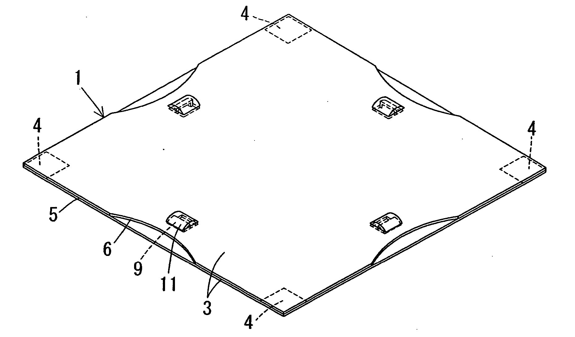
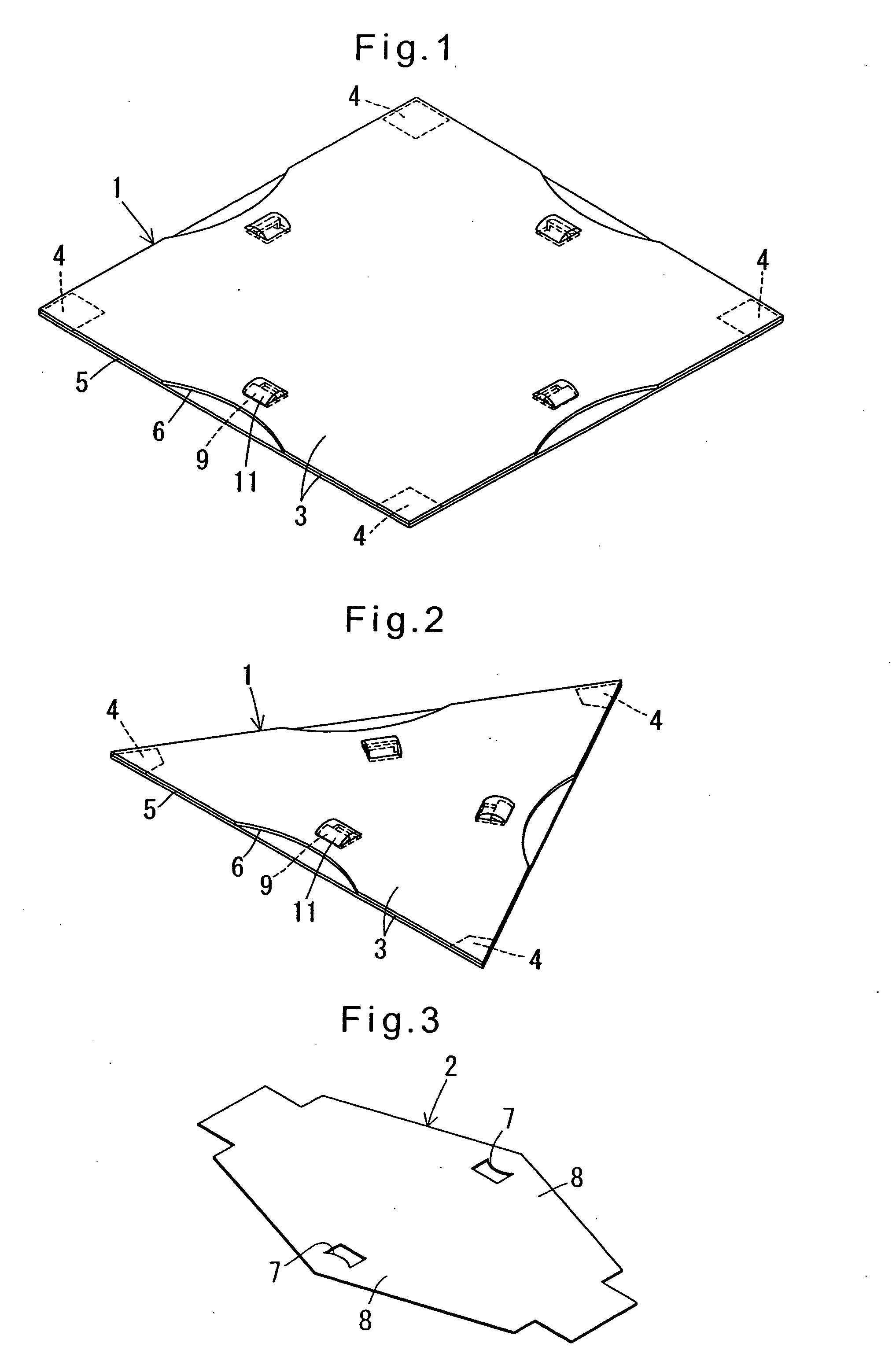
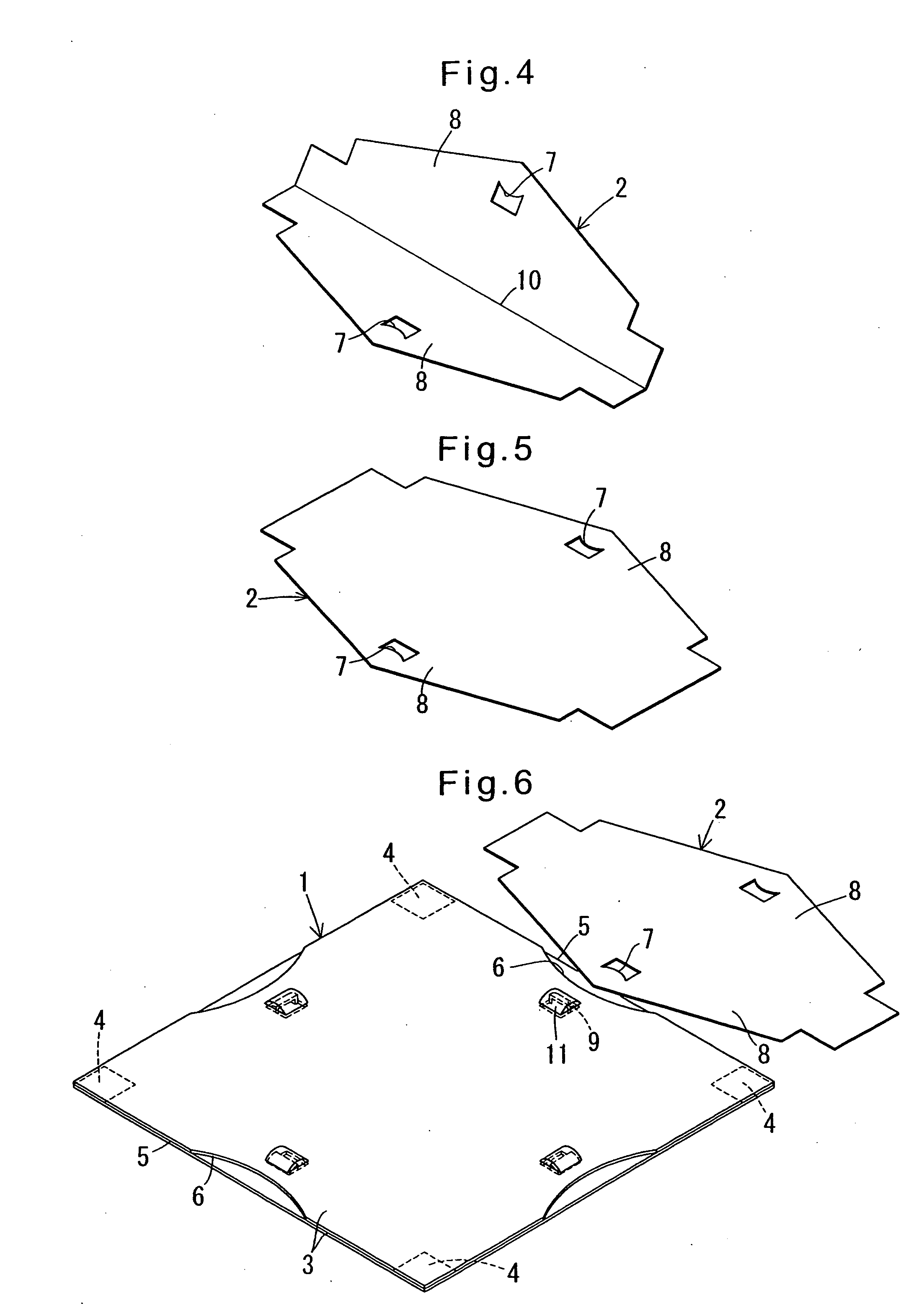
[0052] The assembled block of this embodiment comprises block plates 1 as shown in FIGS. 1 and 2, and joints 2 as shown in FIGS. 3 to 5. The block plates 1 comprise square ones as shown in FIG. 1 and equilateral triangular ones as shown in FIG. 2. All the block plates 1 have edges of equal length and are equal in thickness too.

[0053] The block plates 1 shown in FIGS. 1 and 2 are formed by laminating two flexible plastic base plates 3 (upper and lower plates 3). The two base plates 3 are joined together by e.g. fusing them at joint portions 4 at the corners.

[0054] Except the joint portions 4, the edges of the base plates 3 are not joined together, thus defining receptacles 5 through which a joint 2 can be inserted into between the base plates 3. Each edge of the upper base plate 3 is cut out at its central portion to form an arcuately concave guide pocket 6.

[0055] Slightly inwardly of each edge of the lower...


PUM


Abstract

A block which can be easily assembled into a large variety of shapes and sizes using a smaller number of kinds of joints at a low cost. The assembled block includes equilateral triangular block plates, square block plates, and joints through which the block plates are coupled together. Each of the joints is formed of a single, flexible and bendable plate having wing portions on both sides thereof. The block plates are made of a flexible material and have edges and receptacles each provided along one of the edges for accepting one of the wing portions of the joints. The receptacles are each formed with a guide pocket. Any two the block plates can be coupled together through any of the joints by inserting the respective wing portions of the joint into one of the receptacles of one of the two block plates through the corresponding guide pocket and into one of the receptacles of the other of the two block plates through the corresponding guide pocket.

Description

BACKGROUND OF THE INVENTION [0001] The present invention relates to a three-dimensional block assembled by coupling a plurality of block plates together through joints. [0002] In JP patent 3221637, the applicant has proposed an assembled block comprising square block plates and equilateral triangular block plates that are coupled together through joints. [0003] The block plates and the joints of this block are formed by molding a rigid plastic. Joints are each formed with plugs protruding in at least two directions. Each block plate has receptacles each formed along one of the edges thereof for accepting one of the plugs of the joints. [0004] Different kinds of joints are prepared, i.e. ones having their plugs protruding in two directions in a common plane, ones having their plugs protruding in two directions perpendicular to each other, ones having their plugs protruding in three directions perpendicular to each other, and ones having plugs arranged so that the distances between th...

Claims


Application Information

Patent Timeline
IPC IPC(8): E04C2/04
CPCA63H33/101A63H33/062
Inventor KICHIJO, HIROSHIKICHIJO, YOSHIIE
Owner YOSHIRITSU
Why Eureka
Try Eureka