Luminous display element

a technology of luminous display elements and display elements, which is applied in the direction of discharge tubes/lamp details, natural mineral layered products, solid-state devices, etc., can solve the problems of spoiled display visibility, less efficient light emitted in organic el display elements, and improved emission efficiency, so as to prevent an image, the effect of high contrast ratio and high utilization efficiency of emission

Inactive Publication Date: 2005-05-24
SHARP KK
View PDF39 Cites 25 Cited by
  • Summary
  • Abstract
  • Description
  • Claims
  • Application Information

AI Technical Summary

Benefits of technology

[0023]The main object of the present invention is to provide a luminous display element in which it is possible to prevent an image from being reflected, and contrast ratio and utilization efficiency of emission are high.
[0025]According to the structure, it is possible for the light emitted in the emission layer to emerge to the front side of the luminous display element. Thus, it is possible to realize high lightness and good quality in a white state. Further, it is possible to allow not only the light which is emitted in the emission layer toward the front side, but also the light which is emitted toward the back side to emerge, so that it is possible to improve utilization efficiency of emission.
[0026]Further, it is possible to reflect the ambient light in the same direction as the incident direction by providing the optical member. Thus, for example, contrast ratio of a display device which uses the luminous display element becomes high. Also in a non-emission state, it is possible to reflect the ambient light in the same direction as incident light by providing the optical member, so that the ambient light does not emerge in a direction of an observer. As a result, an image is not reflected, so that it is possible to realize good quality in the black state. Thus, it is possible to provide the luminous display element whose contrast ratio is high.
[0028]According to the structure, it is possible for the light emitted in the emission layer to emerge to the front side of the luminous display element in the first state which is an emission state of the emission layer. Thus, it is possible to realize high lightness and good quality in the white state. Further, it is possible to allow not only the light which is emitted in the emission layer toward the front side, but also the light which is emitted toward the back side to emerge, so that it is possible to improve utilization efficiency of emission.
[0029]Further, when the emission layer is in the second state, an image of a black part of an observer's eye is reflected by including the reflecting member, and the observer recognizes the image of the black part of the eye, so that it is possible to realize the black state. Thus, it is possible to improve contrast ratio of a display device which uses the luminous display element.

Problems solved by technology

Although the organic EL display element is a promising art as a flat panel display, at the same time, it has problems associated with luminance of a material which makes up the organic EL layer, improvement of emitting efficiency, and life-lengthening etc.
However, when an incident angle of light which is incident on a substrate on the side of an observer from which the light emerges, and on an electrode through which the light passes is over a critical angle, the light which is emitted from the organic EL layer such as the luminous polymer is totally reflected, so that the light emitted in the organic EL display element emerges less efficiently.
Thus, like a mirror, reflection of an image occurs in the organic EL display element, so that a visibility of display is much spoiled.
Further, when the strength of the ambient light such as outdoor light is larger than the strength of the light in the organic EL layer, contrast ratio much degrades.
However, ambient light is reflected by the metal electrode also in a direction of an observer, so that contrast ratio of display degrades.
However, by these techniques, the metal electrode and the polarizing film absorb the light which is emitted by the organic EL layer, so that utilization efficiency of emission declines.
The ambient light which is reflected by this portion spoils a black state of a display device, so that contrast ratio degrades.
Thus, by the techniques of the prior arts, it is impossible to obtain a luminous display element which does not allow an image to be reflected, and has high contrast ratio of display and high utilization efficiency of emission.

Method used


Image

  • Luminous display element
  • Luminous display element
  • Luminous display element

Examples


first embodiment

[First Embodiment]

[0055]One embodiment of the present invention is described as follows based on FIG. 1 to FIG. 18(b).

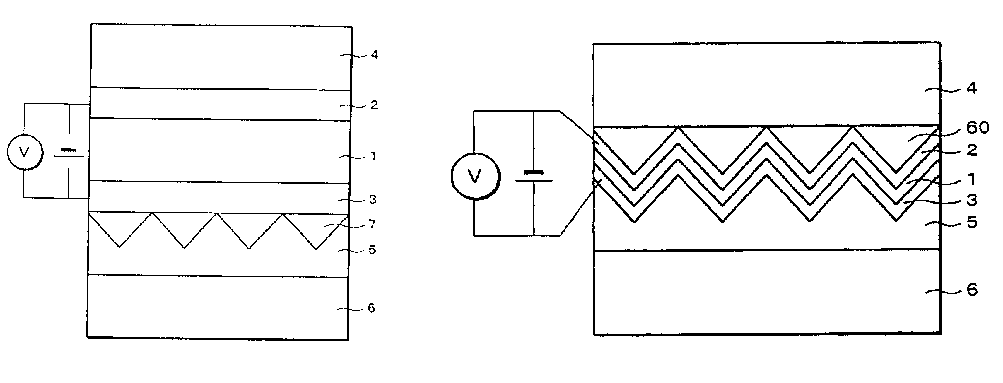
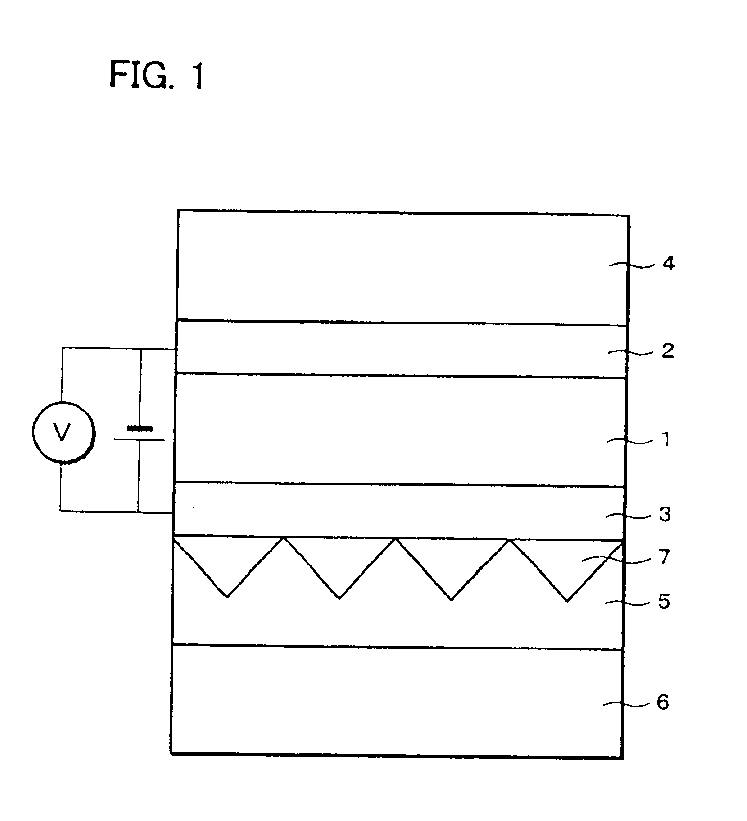
[0056]FIG. 1 is a cross sectional view showing an example of a structure of an organic electroluminescence display element (hereinbelow referred to as organic EL display element), which is a luminous display element. The organic EL display element according to the present embodiment, as shown in FIG. 1, includes an organic electroluminescence layer (hereinbelow referred to as organic EL layer (emission layer)) 1, a transparent electrode 2, an alminium electrode 3, a front side substrate 4, a retro-reflector (optical member, reflecting member) 5, a back side substrate 6, and a flattening film 7.

[0057]The transparent electrode 2, the organic EL layer 1, and the alminium electrode 3 are formed on the front side substrate 4 which is made of materials such as a transparent glass plate and a polymeric film, toward the back side of the organic EL display element in this ord...

second embodiment

[Second Embodiment]

[0153]The second embodiment of the present invention is described as follows based on FIG. 19 to FIG. 24. Note that, components which have the same functions as the components in the first embodiment are given the same numerals, and descriptions thereof are omitted.

[0154]As shown in FIG. 19, an organic EL display element as a luminous display element according to the present embodiment differs from the organic EL display element of the first embodiment in that a louver (first light absorbing member) 101 is provided on the front side substrate 4. Excluding this louver 101, the present embodiment has the same structure as the first embodiment. In the present embodiment, a light control film (Sumitomo 3M products) is used as the louver 101.

[0155]The louver 101 allows light in a range of a view angle which is specified according to the size and the use of a screen of the organic EL display element to pass in a direction of thickness of the front side substrate 4 (that...


PUM

PropertyMeasurementUnit
transmittanceaaaaaaaaaa
thicknessaaaaaaaaaa
thicknessaaaaaaaaaa

Abstract

In a luminous display element, a retro-reflector is provided on the back side of an organic EL layer which includes an emission layer whose state changes between an emission state and a non-emission state. The retro-reflector includes a corner cube array, and reflects incident light in the same direction as an incident direction. A unit structure of the corner cube array is a form of a triangular pyramid which is made up of rectangular equilateral triangles having three faces, and a light shielding process is performed on the periphery of a base angle of the rectangular equilateral triangle. Thus, it is possible to prevent an image from being reflected, so that it is possible to provide the luminous display element whose contrast ratio and the utilization efficiency of emission are high.

Description

[0001]This application is a Divisional of application Ser. No. 09 / 970,821 filed Oct. 5, 2001, now U.S. Pat. No. 6,787,976, the entire content of which is hereby incorporated herein by reference in this application.FIELD OF THE INVENTION[0002]The present invention relates to a luminous display element which displays by using lumination therein.BACKGROUND OF THE INVENTION[0003]An organic electroluminesence display element (hereinbelow referred to as organic EL display element) is an extremely thin, self-light-emitting element. Compared with liquid crystal display elements which are spreading as thin, full-color display elements widely, this organic EL display element is superior in a view angle and speed of response. In this way, it is possible to display at high level, so that the luminous display element such as the organic EL display element is being developed actively so as to be applied to a high-quality display.[0004]The organic EL display element is arranged by providing an org...

Claims


Application Information

Patent Timeline
Patent Type & Authority Patents(United States)
IPC IPC(8): H01L51/52H01J1/70H01J1/00H01L51/50H05B33/22H05B33/24G09F9/30H01L27/32H05B33/00H05B33/10H05B33/12H05B33/14
CPCH01J1/70H01L51/5262H05B33/22H01L51/5281H01L51/5271H10K50/85H10K50/856H10K50/86H05B33/00
Inventor MINOURA, KIYOSHIUEKI, SHUNTOMIKAWA, MASAHIKO
Owner SHARP KK
Why Eureka
Try Eureka