
Radiator core support structure

Inactive Publication Date: 2006-04-20
CALSONIC KANSEI CORP
View PDF7 Cites 24 Cited by
  • Summary
  • Abstract
  • Description
  • Claims
  • Application Information

AI Technical Summary

Benefits of technology

[0010] Further, the overall stiffness of the radiator core support can be improved by the fan shroud portion and the radiator core support upper cover, and particularly, it is possible to prevent, in the event of a light crash of a motor vehicle, deformation of both the radiator core support sides to open outward in the vehicle width direction to thereby cause a crack / damage.
[0011] Moreover, by providing the radiator core support upper cover in a detachable manner, an operation of repairing or replacing the heat exchanger can be easily performed.
[0013] Therefore, impact force in the event of light crash of a motor acts is transferred to both the radiator core support sides through the hood lock stay, so that damaged portions are stopped at the hood lock stay or the radiator core support upper cover, which enables them to be easily replaced for repair, thus suppressing cost of repairing or replacing low.
[0015] Therefore, the radiator core support upper cover can be stably fixed to the fan shroud portion, and thereby increase the overall stiffness of the radiator core support.
[0017] Therefore, the radiator core support upper cover can be stably fixed to the fan shroud portion and the radiator core support sides, and thereby increase the overall stiffness of the radiator core support.

Problems solved by technology

However, in the former conventional radiator core support structure, when the heat exchanger is attached to the radiator core support by inserting it between both the radiator core support sides from an upper side, the heat exchanger comes in contact with the upper radiator core support, becoming an obstacle to its insertion, so that the heat exchanger needs to be fixed in such a way that, after it is inserted between both the radiator core support sides from an obliquely upper side and then its lower portion is fixed to the lower radiator core support, the heat exchanger is raised to stand upright and its upper portion is fixed to the upper radiator core support.
This causes a problem of requiring a lot of labor for attachment as well as a large working space.
This causes a problem of increasing weight and a manufacturing cost.
However, since radiator core supports of recent years are formed integrally using resin or metal, they require a lot of labor and cost to be repaired or replaced.

Method used


Image

  • Radiator core support structure
  • Radiator core support structure
  • Radiator core support structure

Examples


Embodiment Construction

[0030] Hereinafter, an embodiment of the present invention will be described with reference to the accompanying drawings.

[0031] Hereinafter, an embodiment will be explained. First, the entire structure of a radiator core support structure for a motor vehicle will be described.

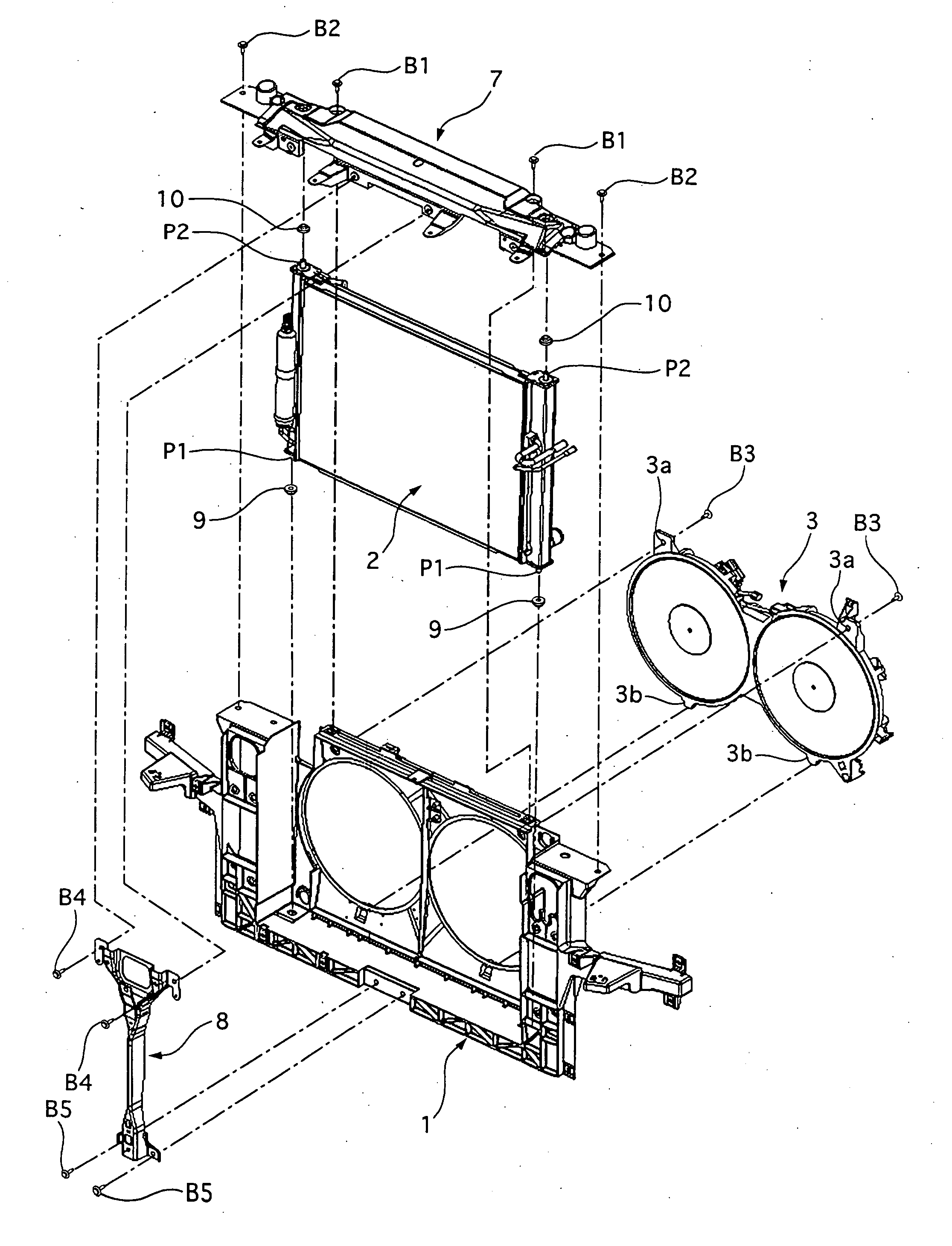
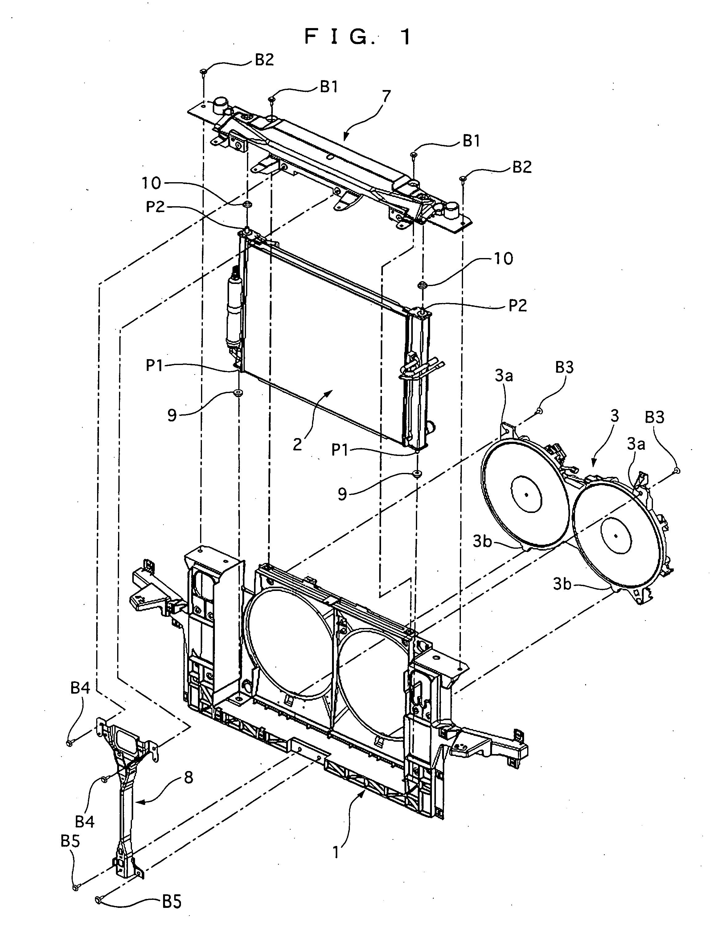
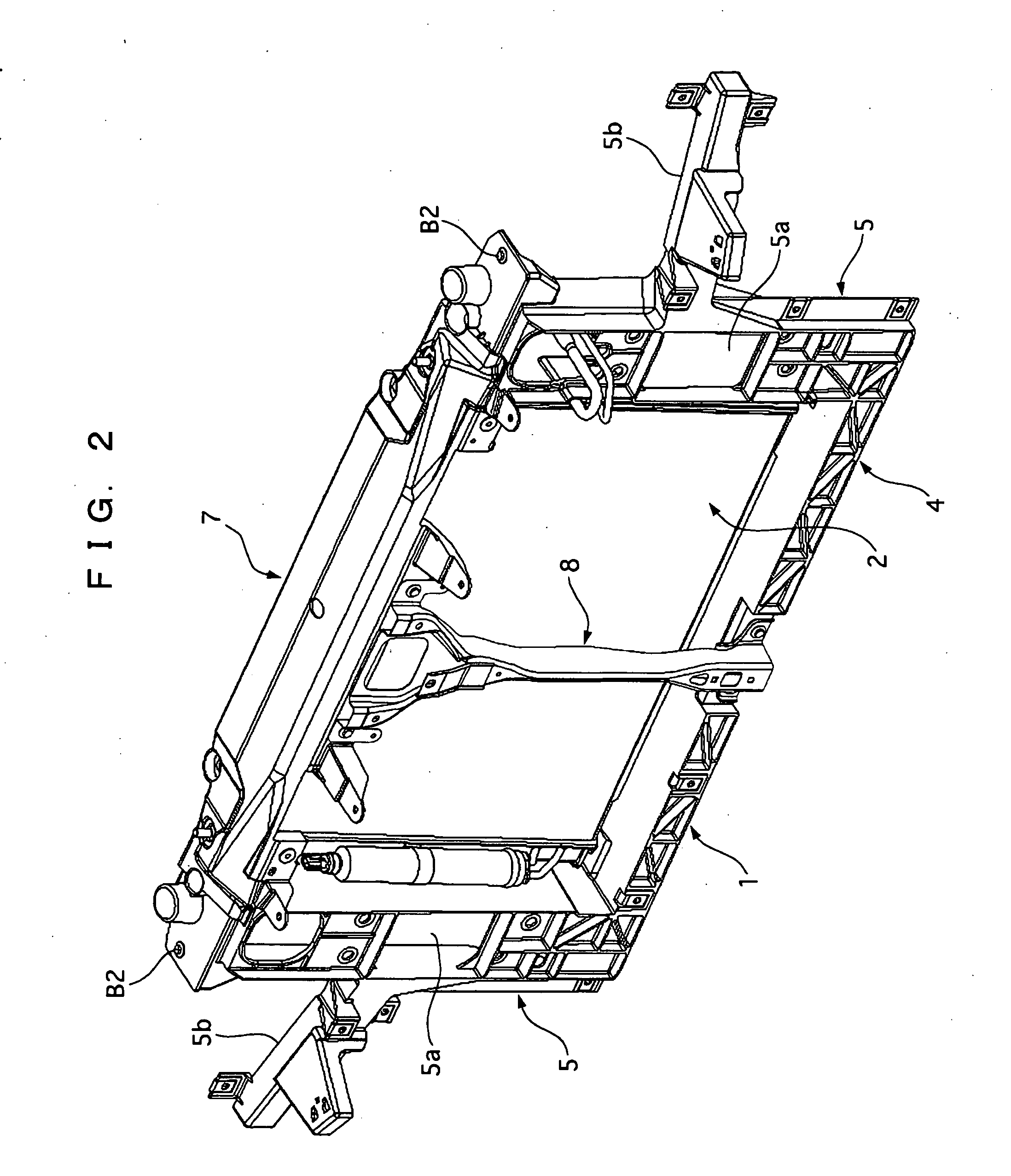
[0032] As shown in FIG. 1 and FIG. 2, the radiator core support structure of this embodiment has a radiator core support 1 mounted on a front side of a vehicle body, a heat exchanger 2 for cooling coolant and cooling medium, and a motor fan 3 for cooling the heat exchanger 3. The heat exchanger 2 and the motor fan 3 are fixed to the radiator core support 1, which will be described below in detail.

[0033] As shown in FIG. 3, the radiator core support 1 has a lower radiator core support 4 extending in a lateral direction of the vehicle body, two radiator core support sides 5 and 5 extending upward respectively from both end portions of the lower radiator core support, and a fan shroud portion 6 provided inside ...


PUM


Abstract

A radiator core support has a lower radiator core support extending in a lateral direction of a vehicle body, radiator core support sides extending upward respectively from both end portions of the lower radiator core support, a fan shroud portion provided inside the lower radiator core support and both the radiator core support sides, and a radiator core support upper cover provided to cover at least an upper side between both the radiator core support sides. The lower radiator core support, both the radiator core support sides, and the fan shroud portion are formed integrally, and the radiator core support upper cover is fixed detachably with respect to the lower radiator core support, both the radiator core support sides, and the fan shroud portion.

Description

BACKGROUND OF THE INVENTION [0001] 1. Field of the Invention [0002] The present invention relates to a radiator core support structure for mounting a heat exchanger on a motor vehicle. [0003] 2. Description of the Related Art [0004] Hitherto, a radiator core support structure for a motor vehicle is described in Japanese Patent Application Laid-open No. 2003-81135, which has an upper radiator core support extending in a lateral direction of a motor vehicle body, a lower radiator core support extending in parallel with the upper radiator core support, radiator core support sides fixing both end portions of the upper radiator core support and the lower radiator core support to each other, and a hood lock stay fixing center portions of the upper radiator core support and the lower radiator core support to each other. [0005] Also, Japanese Patent Application Laid-open No. 2002-19638 discloses a technology on a radiator core support of a type in which the upper radiator core support is om...

Claims


Application Information

Patent Timeline
IPC IPC(8): B60H1/00F28F9/00B60K11/04
CPCB62D25/084
Inventor MIURA, SATORUFURUKAWA, TOSHIHIDEHIRAI, TADAHIRO
Owner CALSONIC KANSEI CORP
Features
  • Generate Ideas
  • Intellectual Property
  • Life Sciences
  • Materials
  • Tech Scout
  • Unparalleled Data Quality
  • Higher Quality Content
  • 60% Fewer Hallucinations
Learn More