Damper device and manufacturing method for damper device

a technology of damper device and manufacturing method, which is applied in the manufacture of springs/dampers, shock absorbers, mechanical devices, etc., can solve the problems of rotor shaft malfunction, and achieve the effects of preventing transmission of vibration energy to the casing, and preventing the concentration of vibration energy to the boundary portion

Active Publication Date: 2006-04-20
SANKYO SEIKI MFG CO LTD
View PDF18 Cites 7 Cited by
  • Summary
  • Abstract
  • Description
  • Claims
  • Application Information

AI Technical Summary

Benefits of technology

[0008] In order to achieve the above object and 
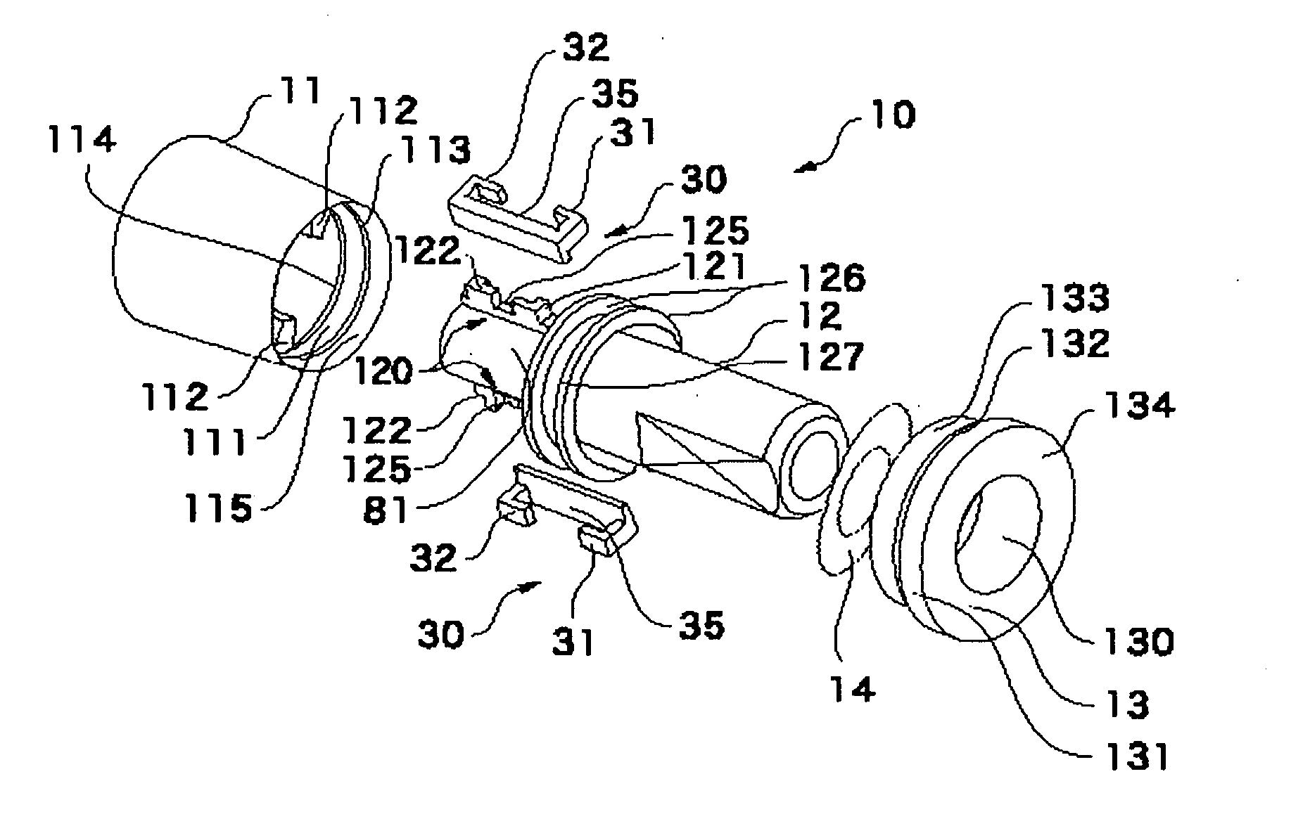
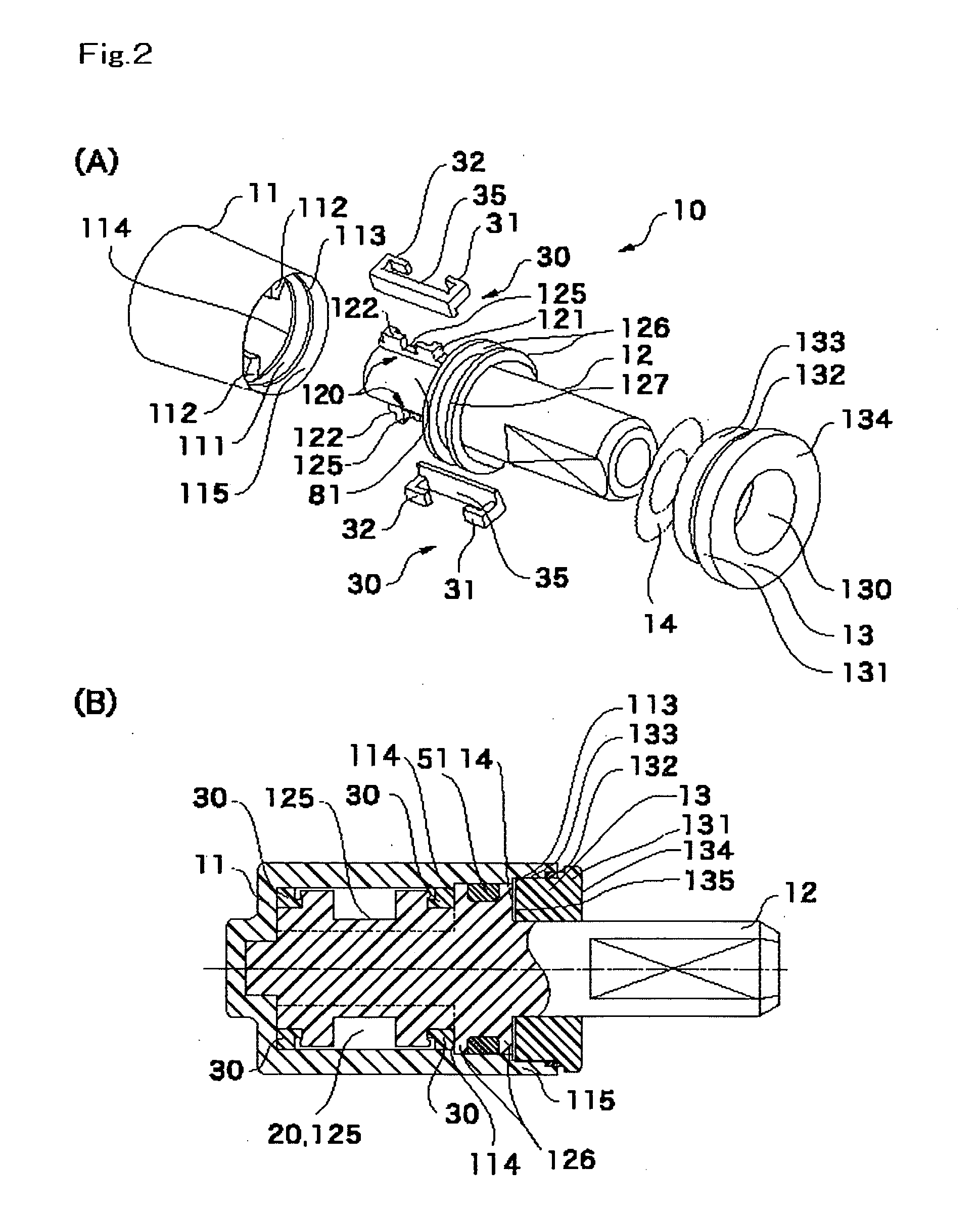
advantage, according to an embodiment of the present invention, there is provided a damper device including a casing provided with an inner circumferential surface formed in a cylindrical shape, a shaft body (turnable shaft) located in the cylindrical space of the casing and supported in a freely turnable manner, a cover which seals the casing, and viscous fluid stored in a sealed space formed between the shaft body and the casing. The casing is provided with a first and a second engagement parts engaging with the cover and the cover is welded with the first engagement part by ultrasonic welding and the second engagement part is used as a positioning part in an axial direction for the cover.
[0009] In this case, it is preferable to be constructed such that the shaft body is provided with a large diameter part which is positioned on the sealed space side of the first and the second engagement parts of the casing and an O-ring for sealing is disposed between the cylindrical inner circumferential surface of the casing and the large diameter part of the shaft body. According to the construction described above, sealing between the inner circumferential surface of the casing and the shaft body is performed on the sealed space side of the casing from the welded portion by ultrasonic welding and the positioning part of the cover in the axial direction which are the first and the second engagement parts. Therefore, the sealed space between the shaft body and the casing can be surely formed.
[0010] In addition, it is preferable to be constructed such that the cylindrical inner circumferential surface of the casing includes a first inner circumferential surface which forms the sealed space in which the viscous fluid is stored, a second inner circumferential surface which faces the large diameter part of the shaft body, and a third inner circumferential surface along which an insert part formed in the cover is inserted into the casing. Further, a first stepped part is formed between the first inner circumferential surface and the second inner circumferential surface so that the second inner circumferential surface has a larger diameter than a diameter of the first inner circumferential surface, and a second stepped part is formed between the second inner circumferential surface and the third inner circumferential surface so that the third inner circumferential surface has a larger diameter than a diameter of the second inner circumferential surface. According to the construction described above, since the second stepped part is formed between the second inner circumferential surface and the third inner circumferential surface, effects due to the ultrasonic welding can be cut off at the second stepped part and effects to the sealing between the inner circumferential surface of the casing and the large diameter part of the shaft body can be prevented. In addition, since the first stepped part is also formed between the first inner circumferential surface and the second inner circumferential surface, effects due to the ultrasonic welding are not transmitted to the sealed space where the viscous fluid is stored.
[0011] In accordance with an embodiment of the present invention, it is preferable that the cover is engaged with the second engagement part, i.e., the positioning part through a washer which is made of material different from the cover. According to the construction described above, vibration energy at the time of ultrasonic welding is cut off by the washer made of a different material from the cover and thus transmission of the vibration energy to the casing can be prevented. Therefore, since the casing is not melted and crushed in the axial direction, the cover can be prevented from being pushed furthermore in the axial direction. For example, in the case that the cover and the casing are made of PBT, the washer may be formed by using PTFE. Preferably, when the washer is made of metal, transmission of vibration energy to the casing can be surely prevented.
[0012] In accordance with an embodiment of the present invention, it is preferable that the washer is disposed so as to be adjacent to the end face in the axial direction of the shaft body. According to the construction described above, since a washer is disposed at a boundary portion between the end face of the shaft body and the cover, concentration of vibration energy to the boundary portion is prevented and thus welding between the end face of the shaft body and the cover can be surely restricted. Further, wear between the end face of the shaft body and the cover can be prevented by the washer.
[0013] In accordance with an embodiment of the present invention, at least an inwardly protruded portion is formed so as to be protruded inward from the inner circumferential surface of the casing such that a gap space is formed between a body part of the shaft body and the inwardly protruded portion. Further, in accordance with an embodiment of the present invention, at least an outwardly protruded portion is formed so as to be protruded outward from the body part of the shaft body such that a gap space is formed between the inner circumferential surface of the casing and the outwardly protruded portion. In addition, in accordance with an embodiment of the present invention, a gap space is formed between the inner circumferential surface of the casing and the outwardly protruded portion at a position where a gap space is formed between the inwardly protruded portion and the body part of the shaft body. According to the construction described above, since ultrasonic welding is performed at the position where a gap space is formed between the body part of the shaft body and the inwardly protruded portion, welding between the inwardly protruded portion and the body part of the shaft body can be prevented. Further, when ultrasonic welding is performed at the position where a gap space is formed between the outwardly protruded portion and the inner circumferential surface of the casing, welding between the outwardly protruded portion and the inner circumferential surface of the casing can be prevented. In addition, when ultrasonic welding is performed at the position where a gap space is formed between the body part of the shaft body and the inwardly protruded portion and a gap space is formed between the outwardly protruded portion and the inner circumferential surface of the casing, welding between the inwardly protruded portion and the body part of the shaft body and welding between the outwardly protruded portion and the inner circumferential surface of the casing can be prevented.

Problems solved by technology

In the worst case, the rotor shaft and the end face of the cover abut with each other to cause malfunction of the rotor shaft.

Method used


Image

  • Damper device and manufacturing method for damper device
  • Damper device and manufacturing method for damper device
  • Damper device and manufacturing method for damper device

Examples


Embodiment Construction

[0025] An embodiment of the present invention will be described below with reference to the accompanying drawings.

[0026]FIG. 1 is an explanatory view of a Western type toilet in which a damper device to which the present invention is applied is used for opening and closing a toilet seat. FIG. 2(A) is an exploded perspective view of a damper device to which the present invention is applied and FIG. 2(B) is its cross-sectional view. FIG. 3 is a front view showing the inside of the case of a damper device to which the present invention is applied. FIG. 4 is a cross-sectional view of a turnable shaft of a damper device to which the present invention is applied. FIGS. 5(A) through 5(D) are explanatory views showing different states of a sealed space during an erected toilet seat is being closed in the damper device shown in FIG. 2. FIG. 5(A) shows the state where the toilet seat 5 is at its completely opened position, FIG. 5(B) shows the state where the toilet seat 5 is closed to a midw...


PUM


Abstract

A damper device having a casing with a cylindrical inner circumferential surface, a shaft body located in the cylindrical space of the casing and supported in a freely turnable manner, a cover which seals the casing, and viscous fluid stored in a sealed space formed between the shaft body and the casing. The casing is provided with a first engagement part and a second engagement part which engage with the cover, and the cover is welded with the first engagement part by ultrasonic welding and positioned by the second engagement part which is used as a positioning part in an axial direction for the cover.

Description

CROSS-REFERENCE TO RELATED APPLICATIONS [0001] This application claims priority to Japanese Application No. 2004-301288 filed Oct. 15, 2004, which is incorporated herein by reference. FIELD OF THE INVENTION [0002] The present invention relates to a damper device utilizing fluid pressure and a manufacturing method for the damper device. BACKGROUND OF THE INVENTION [0003] In recent years, a damper device has been used which is mechanically connected to a toilet seat or a toilet lid of a Western type toilet by taking into consideration of user's convenience when the toilet seat or the toilet lid is opened or closed. [0004] In the damper device, a rotor shaft is disposed in the inside of a casing and oil (viscous fluid) is stored in a sealed space formed between the rotor shaft and the casing. The sealed space is formed by the casing incorporated with a cover after the rotor shaft is inserted into the inside of the casing and oil is stored between the rotor shaft and the casing (see, fo...

Claims


Application Information

Patent Timeline
Patent Type & Authority Applications(United States)
IPC IPC(8): F16D57/00
CPCF16F9/145F16F2226/048
Inventor IWASHITA, HIROYUKI
Owner SANKYO SEIKI MFG CO LTD
Why Eureka
Try Eureka