Plating apparatus and plating method

a technology of plating apparatus and plating film, which is applied in the direction of electrolysis components, manufacturing tools, and semiconductor/solid-state device details, etc., can solve the problems of imposing a limitation on affecting the quality of the plating, and small footprint, so as to enhance the in-plane uniformity of the plated film thickness, good gas-bubble releasability

Inactive Publication Date: 2006-04-20
EBARA CORP
View PDF5 Cites 44 Cited by
  • Summary
  • Abstract
  • Description
  • Claims
  • Application Information

AI Technical Summary

Benefits of technology

The present invention aims to provide a plating apparatus and method that can improve the uniformity of plating thickness by using a dipping method with good gas-bubble releasability. The invention achieves this by regulating the flow of plating solution in the tank.

Problems solved by technology

The technical problem addressed in this patent text is the limitation of the in-plane uniformity of plating in conventional plating apparatuses during the dipping method. The plating solution flows in a tank and the paddles stir the solution to form a plated film on the substrate. However, it is difficult to securely fill in via holes with a metal film by plating while preventing defects. The plating apparatus needs to adjust the regulation plate and remove the plated metal that has adhered to the substrate. A plating apparatus with a simple structure and easily-maintained mechanism is in demand.

Method used


Image

  • Plating apparatus and plating method
  • Plating apparatus and plating method
  • Plating apparatus and plating method

Examples


Embodiment Construction

[0089] Preferred embodiments of the present invention will now be described with reference to the drawings. The following description illustrates the case of using a substrate, such as a semiconductor wafer, as an object to be plated.

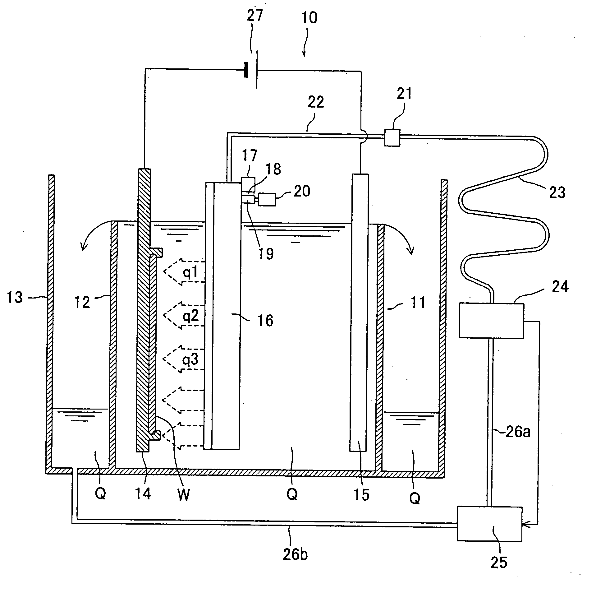
[0090]FIG. 6 is a schematic vertical sectional view of a plating apparatus according to an embodiment of the present invention, and FIG. 7 is a plan view showing the arrangement of a substrate holder, an anode and plating solution jet nozzles in a plating tank. The plating apparatus 10 is an electroplating apparatus, and includes a plating tank 11 for holding therein a plating solution Q, and an overflow tank 13 for holding the plating solution Q that has overflowed the upper end of the overflow weir 12 of the plating tank 11. In the plating tank 11, a substrate W, which is held by a substrate holder 14, and an anode 15, both immersed in the plating solution Q, are disposed vertically and opposite to each other at a predetermined distance. Plating solu...


PUM

PropertyMeasurementUnit
Widthaaaaaaaaaa
Distanceaaaaaaaaaa
Current densityaaaaaaaaaa

Abstract

A plating apparatus employs a dipping method with good gas-bubble releasability and, by regulating the flow of plating solution in a plating tank, can enhance the in-plane uniformity of a thickness of a plated film. The plating apparatus includes a plating tank for holding a plating solution, a plating solution jet nozzle having a slit-like plating solution jet orifice for jetting the plating solution toward a surface to be plated of an object to be plated disposed in the plating tank, and a plating solution supply section for supplying the plating solution to the plating solution jet nozzle.

Description


Claims


Application Information

Patent Timeline
Owner EBARA CORP
Why Eureka
Try Eureka