Non-refillable valve

a non-refillable, valve technology, applied in the direction of functional valve types, water supply installation, operating means/releasing devices of valves, etc., can solve the problem of not being able to refill containers, etc., and achieve the effect of simple and reliable construction

Inactive Publication Date: 2006-04-20
DISCOUNT REFRIGERANTS
View PDF32 Cites 23 Cited by
  • Summary
  • Abstract
  • Description
  • Claims
  • Application Information

AI Technical Summary

Benefits of technology

[0007] One object of the present invention is to provide a non-refillable valve for pressure containers, for example, cylinders used in industrial applications to hold and store pressurized industrial gas. Another object of the invention is to provide a valve which easily permits discharge of the pressure container, but will automatically prevent refilling of the container without the user or operator of the valve having to further manipulate the valve. Another object of the invention is to provide the above described functionality with a valve of simple and reliable construction.
[0013] The valve core may be one integral unit made of a resilient material, such as natural or synthetic rubber. Alternatively, the valve core may include a valve core body, and a sealing member which includes a resilient sealing surface for engagement with the valve seat. The valve core flange can also be shaped to accommodate the particular constriction formed within the chamber. The valve core flange can be shaped or configured allowing it to be compressed or moved downwardly past the constriction without undue force, yet the valve core flange configuration makes it much more difficult to return the valve core to its first position. For example, the lower end of the valve core flange can be slightly tapered, while the upper end can have a distinct edge or corner preventing it from being easily forced upwardly beyond the constriction.
[0015] As the valve stem advances, it seats a sealing portion or sealing member of the valve core against a valve seat at the distal end of the lower portion of the chamber of the valve body. This action also permanently disengages the retaining means, and allows the valve core to thereafter freely move longitudinally within the lower portion of the valve chamber in response to fluid pressure applied to the valve core. Therefore, upon opening the valve, the fluid pressure within the container forces the valve core to disengage from the valve seat, and the fluid from the container is released. The valve may be operated any number of times to selectively release the fluid from the container as desired. Upon attempted refilling of the container using a pressurized fluid, the valve core seats against the valve seat, thereby preventing fluid from refilling the container to which the valve is attached.

Problems solved by technology

Thus, such pressure containers can be initially charged or filled with the refrigerant; however, once the refrigerant has been discharged from the container, the container may not be refilled again.

Method used


Image

  • Non-refillable valve
  • Non-refillable valve
  • Non-refillable valve

Examples


first embodiment

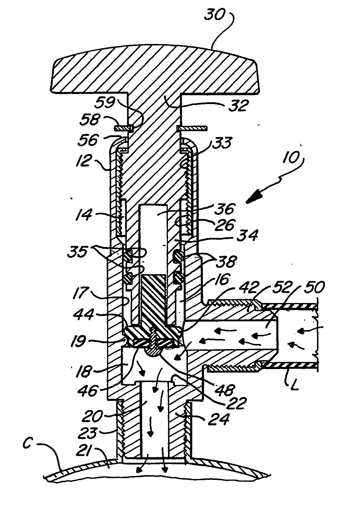
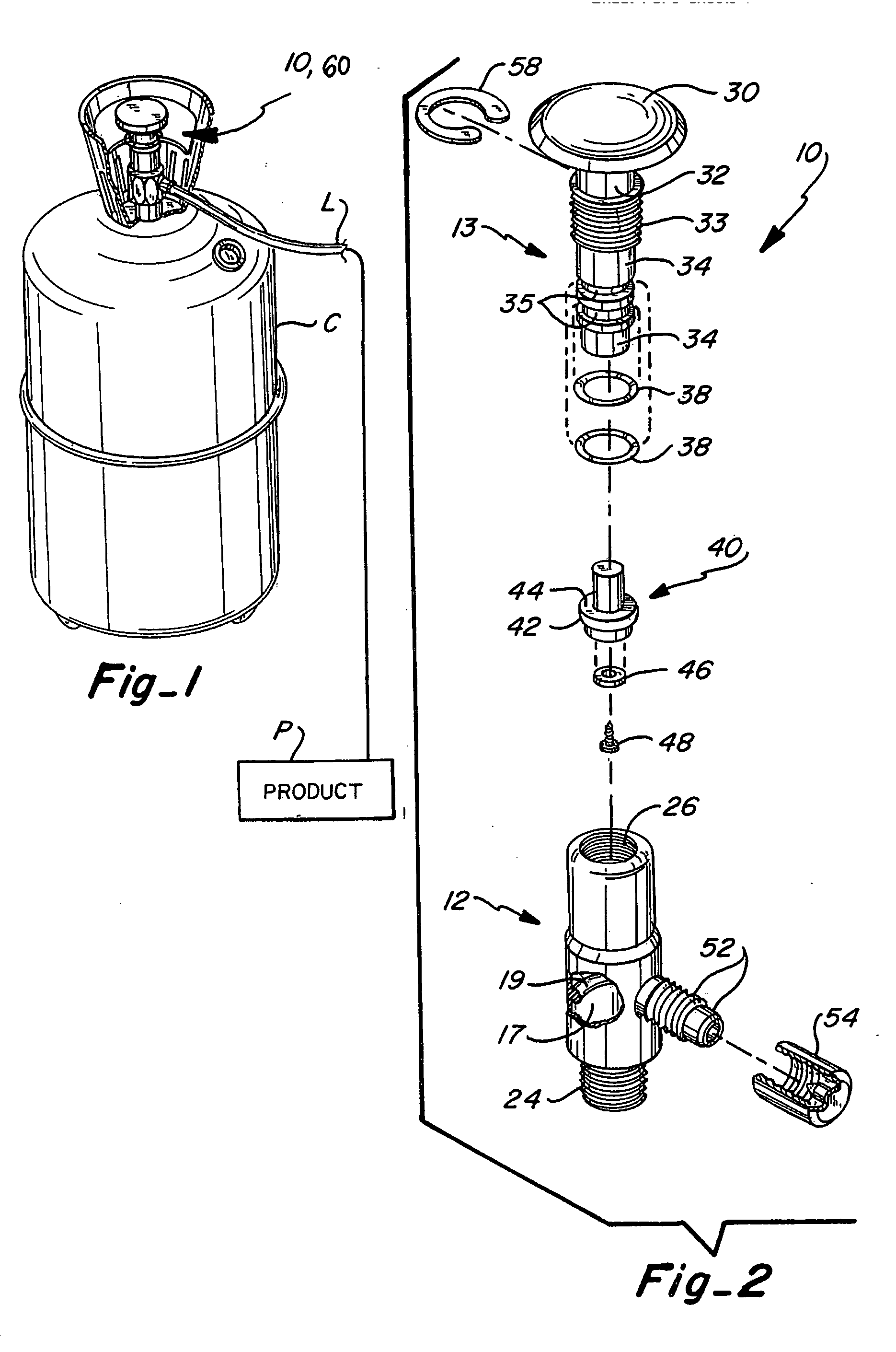
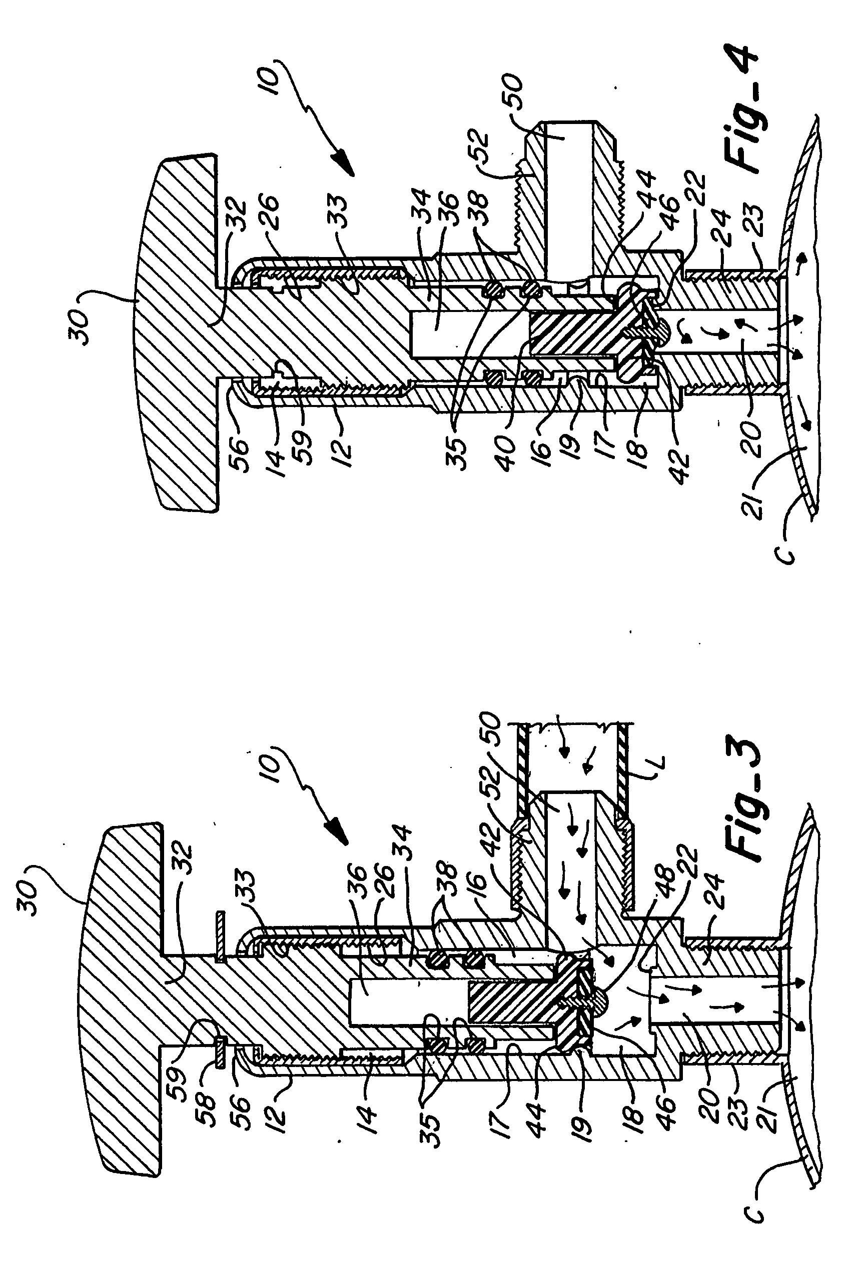
[0032] Now referring to FIGS. 2 and 3, the primary components of the present invention, namely valve 10, include a valve body 12 and a valve operating assembly 13, including a number of working parts which are received in the valve body when assembled. The valve body 12 is a cylindrical shaped member including a chamber extending longitudinally therethrough. When the valve operating assembly 13 is positioned within the chamber, the chamber can be conceptually separated into an upper portion 14, a middle portion 16, and a lower portion 18. As well understood by those skilled in the art, the valve body may be made of a suitable metal such as aluminum or stainless steel. The inner or interior surface 17 defining the chamber of the valve body includes a restriction or constriction 19, shown in the form of a machined inner concentric rim 19 formed on the inner surface 17. In lieu of a continuous concentric rim, this feature could include one or more segmented protrusions formed on the in...

second embodiment

[0039] Referring now to FIGS. 7-11, a non-refillable valve is shown as valve 60. As discussed in the following paragraphs, valve 60 shares a number of characteristics to valve 10 described above. Valve 60 comprises a valve body 64 that is a substantially cylindrical shaped member including a chamber 68 extending longitudinally therethrough. Valve 60 further includes a valve operating assembly 70, including a number of working parts that are received in the valve body 64 when assembled.

[0040] A handle 30 is provided for manipulating the valve operating assembly 70. The handle 30 connects to, or is integral with a valve stem 74 that extends into chamber 68 of valve body 64. As shown, an upper portion 76 of the valve stem 74 has an externally threaded area 33 that is threaded into the upper portion 80 of the chamber 68. The upper portion 80 of chamber 68 preferably includes a set of matching internal threads 84 for cooperating with the threaded area 33 of the valve stem 74. Alternative...


PUM


Abstract

A non-refillable valve is provided that allows for an initial filling of a container, but prevents subsequent refilling of the container. In one embodiment, the valve includes a valve core having a retaining means for maintaining the valve core in an open or non-sealing position to allow flow through the valve and filling of the container. The valve core may then be advanced to seal the container, and subsequently selectively operated to discharge the container as desired. Further refilling of the container is prevented by the force of fluid reentering the valve which forces the valve core to its seated engagement with the valve seat.

Description

CROSS REFERENCE TO OTHER APPLICATIONS [0001] Cross reference is made to pending U.S. patent application Ser. No. 10 / 971,335 filed Oct. 22, 2004, which is a continuation application of U.S. patent application Ser. No. 10 / 622,043 filed on Jul. 16, 2003, now U.S. Pat. No. 6,808,159 issued Oct. 26, 2004, which is a continuation application of U.S. patent application Ser. No. 09 / 948,328 filed on Sep. 6, 2001, now U.S. Pat. No. 6,595,486 issued, Jul. 22, 2003. The entire contents of the above referenced patent applications are incorporated herein by reference in their entirety.FIELD OF THE INVENTION [0002] This present invention relates to non-refillable valves used in pressurized systems. More particularly, the present invention relates to non-refillable valves adapted for use with pressurized vessels or containers wherein the construction of the valves allow the pressure container to be filled once, and then selectively discharged; however, subsequent refilling of the pressure container...

Claims


Application Information

Patent Timeline
Patent Type & Authority Applications(United States)
IPC IPC(8): F16K51/00
CPCH01F17/0006H01F19/04H01F27/2804H01F2017/0046Y10T137/88054Y10T137/8811
Inventor CONG, JING JIE
Owner DISCOUNT REFRIGERANTS
Why Eureka
Try Eureka