
NMR MAS inflow bernoulli bearing

a technology of bernoulli bearing and nmr mas, which is applied in the direction of magnetic circuit rotating parts, magnetic circuit shapes/forms/construction, instruments, etc., can solve the problem that the axial pressure over the conical rotor end may then exceed the atmospheric pressure by a substantial amount, and achieve the effect of improving stability and stiffness

Active Publication Date: 2006-04-20
DOTY SCI
View PDF13 Cites 19 Cited by
  • Summary
  • Abstract
  • Description
  • Claims
  • Application Information

AI Technical Summary

Benefits of technology

This patent describes an improvement to an axial gas bearing used on a gas-driven NMR machine. By creating a space where there is no outgoing motion, this new design uses inward flow to achieve better stability and higher performance. Injection of air through tiny holes results in a strong backward force which helps keep the rotor stable during operation. Additionally, the use of a micoturbine provides motive power without interfering with automated samples changing. Overall, these improvements make it possible to reach faster speeds while maintaining accuracy in magnetic resonance imaging (MRI).

Problems solved by technology

The technical problem addressed in this patent is the inability of current methods to improve the resolution in NMR spectroscopy of solids by using high-speed spinners. The invention proposes an axial air bearing that utilizes inward flow with minimal rotational component over a rotor conical end to achieve improved stability and stiffness without the need for very-low-back-pressure venting. The invention is compatible with automatic sample change and can be used in a variety of applications.

Method used


Image

  • NMR MAS inflow bernoulli bearing
  • NMR MAS inflow bernoulli bearing
  • NMR MAS inflow bernoulli bearing

Examples


Embodiment Construction

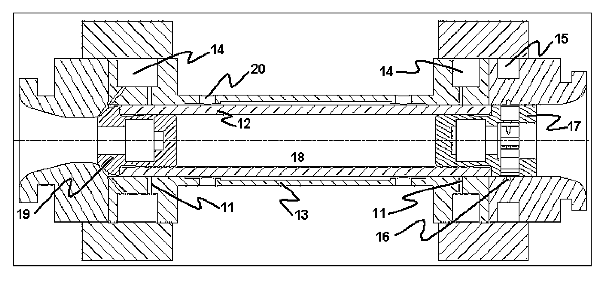
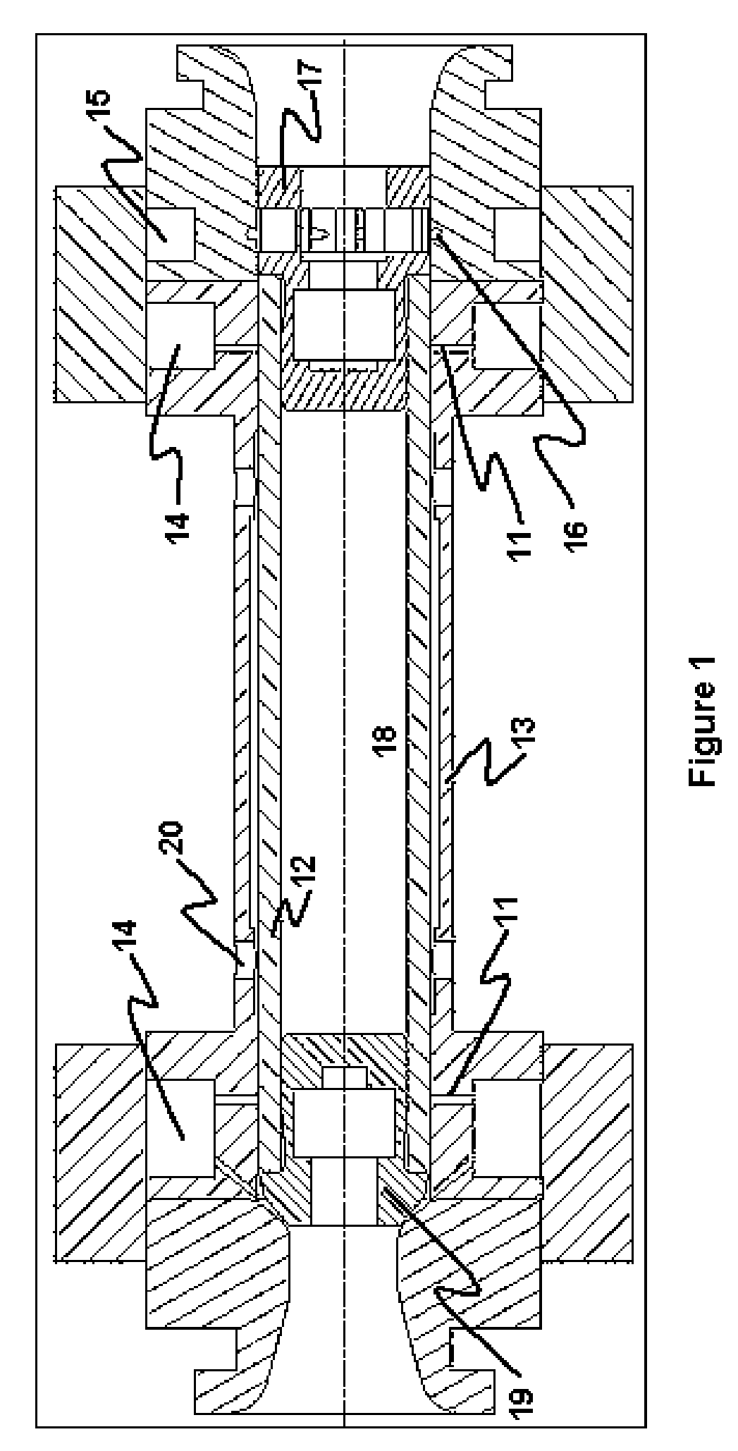
[0031] The high-speed NMR sample spinner shown in FIG. 1 has hydrostatic air radial bearing orifices 11 introducing pressurized gas radially to support the ceramic rotor 12 near both ends inside the ceramic cylindrical stator 13, according to the prior art. Note that these orifices are referred to as radial for convenience, as they establish radial support, but in practice they are typically offset from a purely radial direction. Bearing manifolds 14 are provided for distribution of air to the radial bearing orifices of throat diameter d1, and a drive manifold 15 is provided for distribution of air to the tangentially directed drive nozzles 16, which enable the microturbine 17 at the “top” or “front” of the rotor to spin the rotor 12 and its NMR sample 18. The axial bearing tip 19 is pressed into the “bottom” or “rear” of the rotor. The preferred radial bearing orifice throat diameter d1 is typically about 0.1 mm for a rotor of 2 mm outside diameter, and it is about 0.25 mm for a 14...


PUM


Abstract

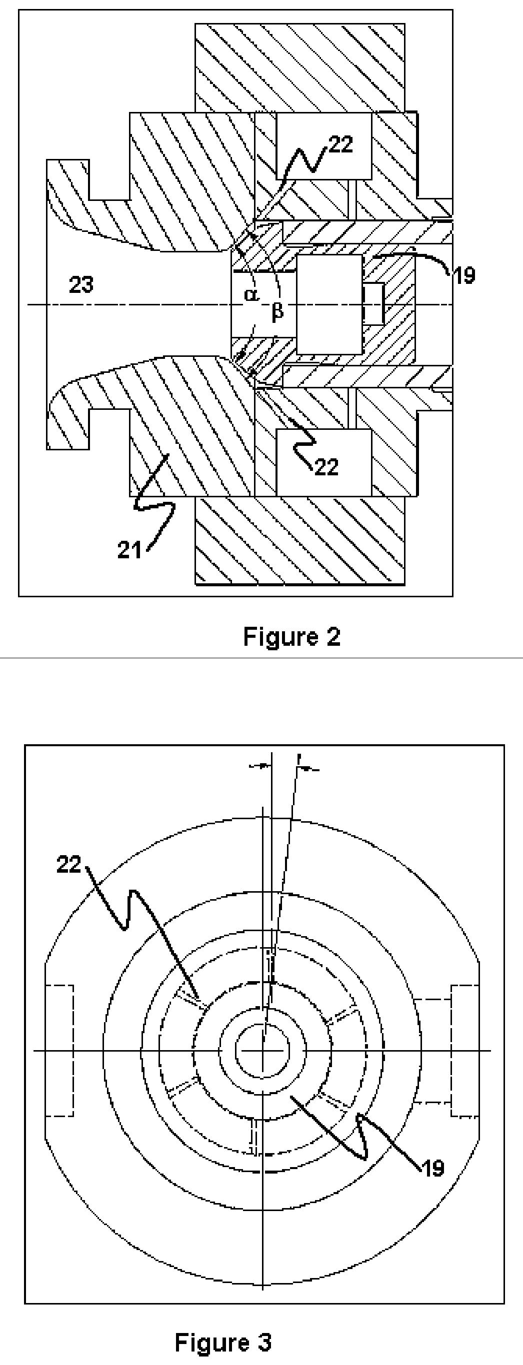
An improved axial gas bearing for a gas-driven NMR MAS sample rotor is disclosed that utilizes inward flow with a low rotational component over a rotor conical end. A conical flow region is formed between the rotor conical end and a conical stator bearing surface such that the included angle defining the stator surface is not less than the included angle defining the rotor conical end. Gas is injected radially inward with a significant axial rearward component from a number of small holes at high velocity from the periphery into the conical flow region. Compared to the radial velocity components, the tangential flow components of the injected gas are small and preferably opposed to the direction of the rotor rotation. The high and accelerating negative radial velocities may result in significant Bernoulli effect, such that the mean axial pressure over the conical rotor end may be less than atmospheric pressure for a given axial clearance, but as the clearance decreases, the hydrostatic effects exceed the Bernoulli effects and the mean axial pressure over the conical rotor end may then exceed atmospheric pressure by a substantial amount. Thus, a self-stabilizing axial bearing is formed with improved stability and stiffness for rotor surface speeds up to at least 80% of the speed of sound. Motive power required to spin the rotor may be provided by a radial-inflow microturbine at the opposite end of the rotor in a way that is readily compatible with automatic sample change.

Description


Claims


Application Information

Patent Timeline
Owner DOTY SCI
Learn More