Surface mount magnetic component assembly

Inactive Publication Date: 2006-04-20
STANDEX ELECTRONICS
View PDF2 Cites 6 Cited by
  • Summary
  • Abstract
  • Description
  • Claims
  • Application Information

AI Technical Summary

Benefits of technology

[0012] The primary and secondary terminals can be molded in place during the manufacture of the header or are rigidly attached to the header by other suitable means. The molded header holds the primary and secondary terminals 18 rigidly in position and maintains the coplanarity of the primary and secondary terminals. The header also facilitates assembly of the planar magnetic device, such as a planar transformer or planar inductor, which may have one or more coils.
[0013] The raised sidewalls assist in the alignment of the core assembly by guiding the core assembly into position on the pins of the primary and secondary terminals. The two nonterminal sides of the header, i.e., the side bars, allow the core to sit lower than prior art planar transformers. In addition to assisting in alignment during assembly, the raised sidewalls make the entire assembly stronger since they provide a large bonding surface. The core is bonded or glued to the side bars and the raised sidewalls making an integrated package that holds together better than prior art planar transformers and planar inductors. When the planar magnetic device

Problems solved by technology

The main difficulty in packaging high frequency power transformers and multi-winding inductors for surface mounted device applications is to provide accurate coplanarity of the device terminals during manufacturing and installation on the mounting surface or substrate.
These prior art devices have been a problem in many applications because of the height of the device makes it unsuitable or difficult to use in low profile converters and power supplies.
In addition, these prior art devices have presented cooling problems in that the plastic heade

Method used


Image

  • Surface mount magnetic component assembly
  • Surface mount magnetic component assembly
  • Surface mount magnetic component assembly

Examples


Example

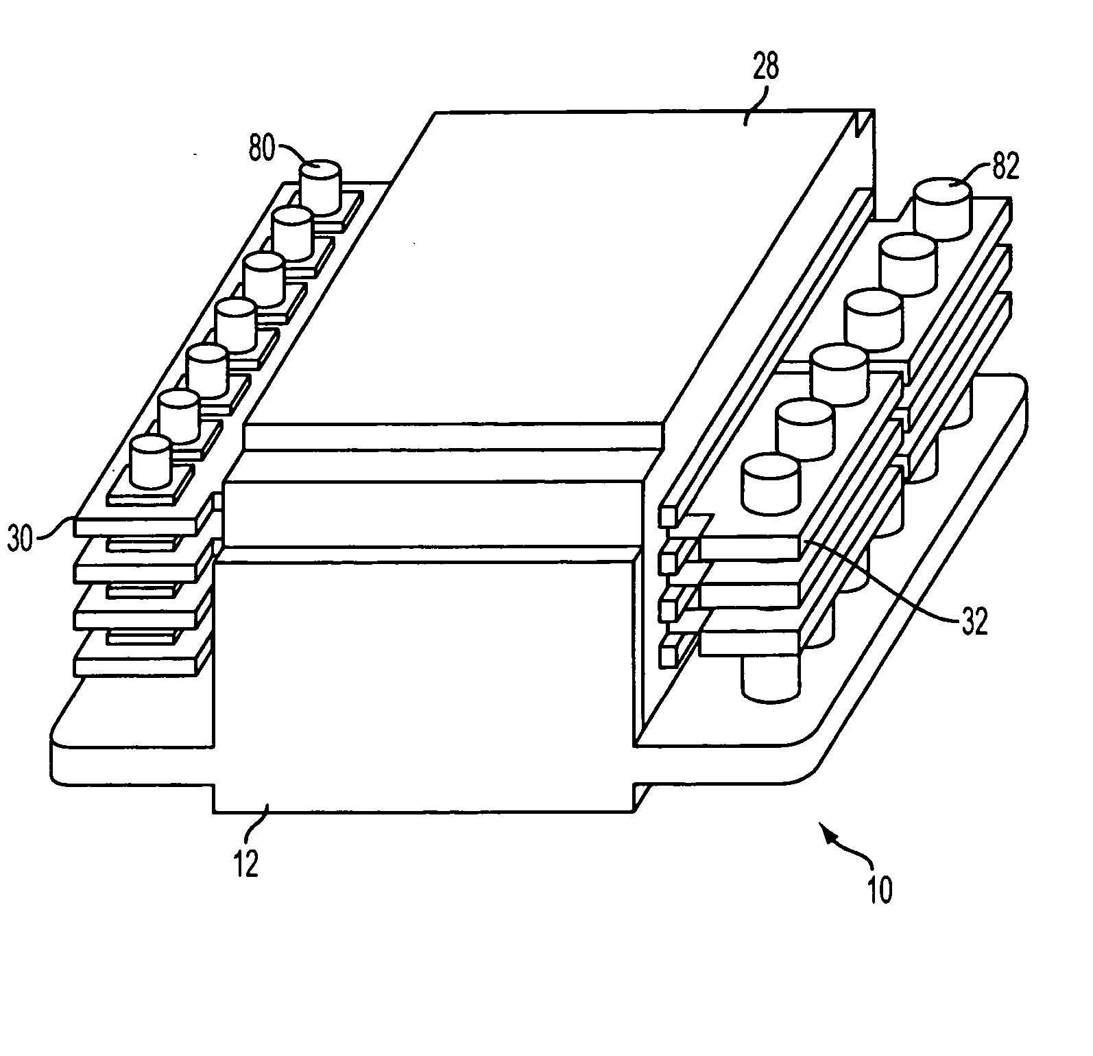
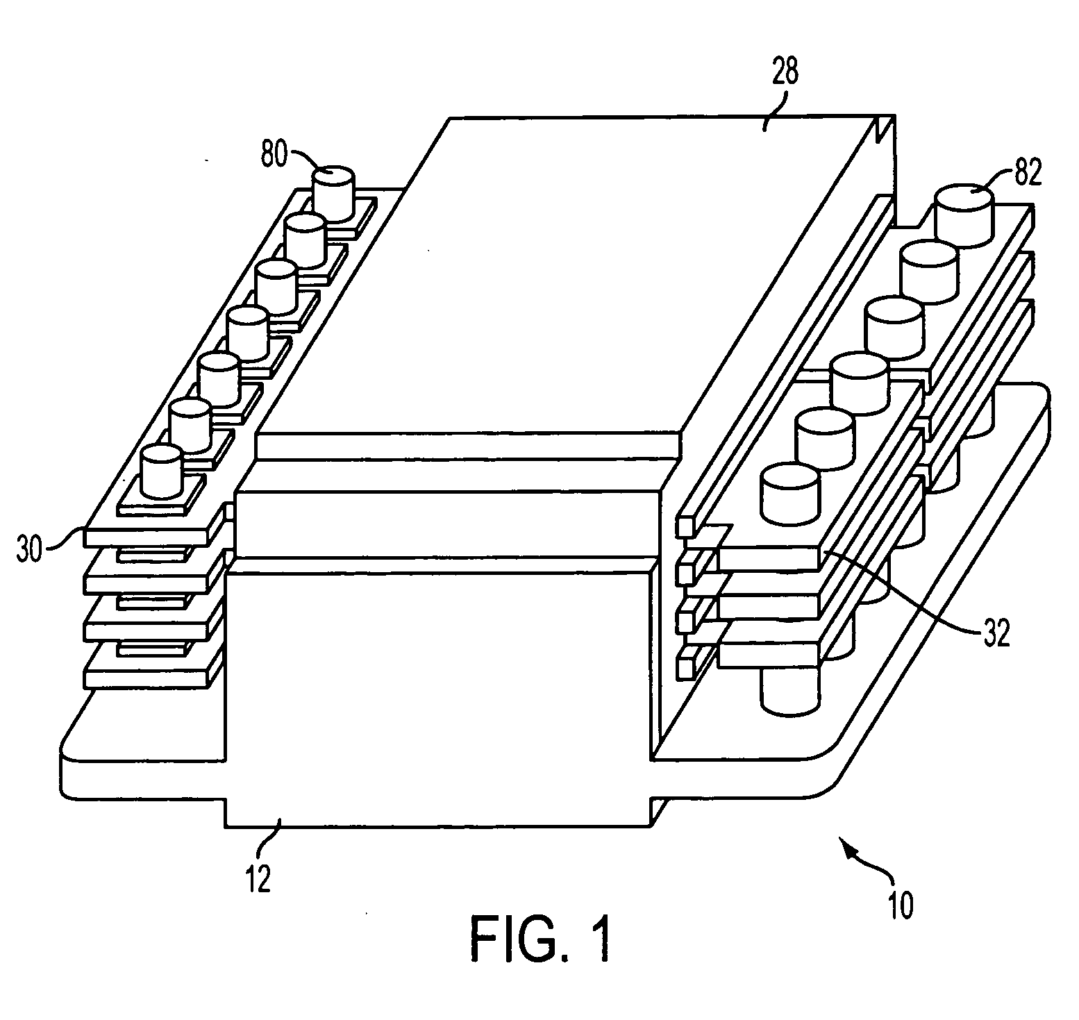
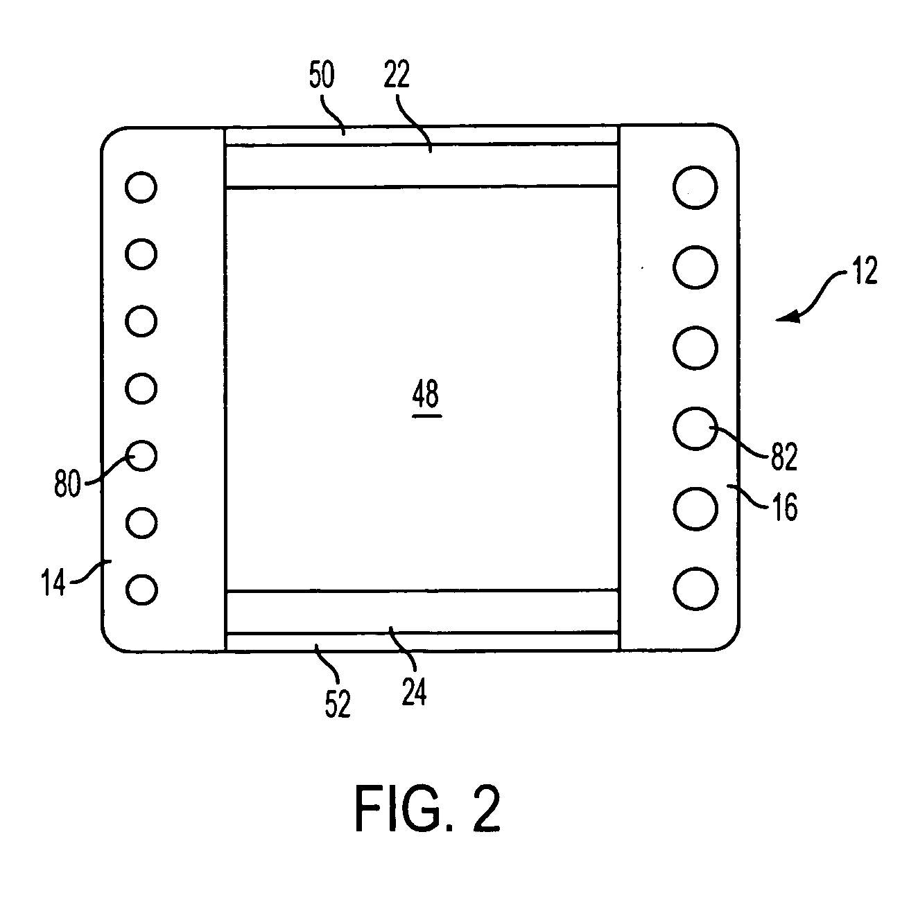
[0026] Referring to FIGS. 1-9, a planar transformer 10 has a header 12 which has a generally rectangular shape; however, other shapes, such as circular, can be used. Header 12 is made of plastic or other suitable material that is rigid and nonconductive, for example, ceramic. Header 12 has terminal sides 14 and 16 which are located on opposite sides of header 12. Terminal side 14 has a plurality of primary terminals 18 with heads 60 and pins 80, and terminal side 16 has a plurality of secondary terminals 20 with heads 62 and pins 82. Primary terminals 18 and secondary terminals 20 can be made of, for example brass or copper, or other suitable materials, as is known in the art. Primary terminals 18 and secondary terminals 20 are molded in place in terminal sides 14 and 16, respectively, during the manufacture of header 12 or rigidly attached to header 12 by other suitable means. Heads 60 of primary terminals 18 are adjacent bottom side 54 of terminal side 14, and pins 80 pass through...


PUM


Abstract

A planar magnetic device comprising a molded header and a planar core assembly, and a method of making a planar magnetic device. The molded header has first, second, third, and fourth sides and an aperture in the center. The first side has a plurality of terminals positioned through it. The third and fourth sides have upper surfaces that are lower than the upper surfaces of the first side. The planar core assembly comprises planar windings and a core. One side of the planar winding has a plurality of terminals with through-holes so that the primary terminals of the header are positioned through the through-holes. The core surrounds at least a portion of the planar windings. The core is shaped so that a first portion of the core is positioned in the aperture, a second portion of the core is positioned on the upper surface of the third side, and a third portion of the core is positioned on the upper surface of the fourth side.

Description

CROSS-REFERENCE TO RELATED APPLICATIONS [0001] Not applicable STATEMENT REGARDING FEDERALLY SPONSORED RESEARCH OR DEVELOPMENT [0002] Not Applicable FIELD OF THE INVENTION [0003] The invention relates generally to surface mount magnetic component assemblies, and more particularly, to an improved low-profile coplanar surface mount magnetic component assembly. BACKGROUND OF THE INVENTION [0004] The main difficulty in packaging high frequency power transformers and multi-winding inductors for surface mounted device applications is to provide accurate coplanarity of the device terminals during manufacturing and installation on the mounting surface or substrate. Prior art headers have used a solid plastic base with molded copper or brass terminals to prevent terminal to wire or terminal to planar winding connection from re-flow during installation and losing coplanarity with other terminals and with the bottom of the core. The ferrite cores have been mounted on the top of the plastic head...

Claims


Application Information

Patent Timeline
IPC IPC(8): H01F27/29
CPCH01F27/2804H01F27/292H01F27/306H01F2027/2819
Inventor ESTROV, ALEXANDER
Owner STANDEX ELECTRONICS
Why Eureka
Try Eureka