
Ink cartridge usable with a wide array type printer head

a wide array type, printer head technology, applied in printing and other directions, can solve the problems of deteriorating filter performance, reducing the compression effect of foam, deteriorating the supply performance and use efficiency of ink absorbed, etc., and achieves the effect of smooth ink flow

Inactive Publication Date: 2006-04-20
SAMSUNG ELECTRONICS CO LTD
View PDF11 Cites 3 Cited by
  • Summary
  • Abstract
  • Description
  • Claims
  • Application Information

AI Technical Summary

Benefits of technology

[0011] The present general inventive concept provides an ink cartridge usable with a wide array type printer head capable of preventing deformation and performance degradation of a filter. The ink cartridge supplies sufficient ink required by the wide array type printer head, and maintains compression of foam inserted into the ink cartridge.
[0014] The bottom surface of the ink cartridge body may include the at least one ink pipe with a plurality of inlet ports each having an area so that sufficient ink required by the wide array type printer head may be supplied thereto. Additionally, a smaller area maintains compression of foam used to absorb the ink in the ink storage space and prevent deformation of a filter used to filter dust from the at least one ink pipe.
[0016] The at least two inlet ports of the at least one ink pipe may be spaced apart from each other so that a compression efficiency of the foam inserted in the ink cartridge body may be increased by this spaced arrangement compared to an arrangement in which the at least two the inlet ports of the at least one ink pipe are disposed adjacent to each other. As a result of this spaced arrangement, the ink cartridge body smoothly supplies the ink to the printer head.
[0021] The second channel may be located closer to the bottom surface of the ink cartridge body than the at least one first channel. That is, bottom surfaces of the first and second channels may be disposed to form a step, thereby making the second channel have a capacity larger than the at least one first channel. In addition, since the ink cartridge body is generally manufactured using an injection mold, when the first and second channels are made to have the same height, a slide core of the injection mold is more deeply inserted therein, thereby making the ink cartridge more difficult to manufacture.
[0024] At least a portion of the second channel may be in direct fluid communication with the bottom end of the at least one ink pipe such that ink is received in the second channel without flowing through the at least one first channel. The bottom end of the at least one ink pipe may be in fluid communication with the second channel having a capacity larger than the first channel, thereby maintaining a smooth ink flow between the first and second channels.

Problems solved by technology

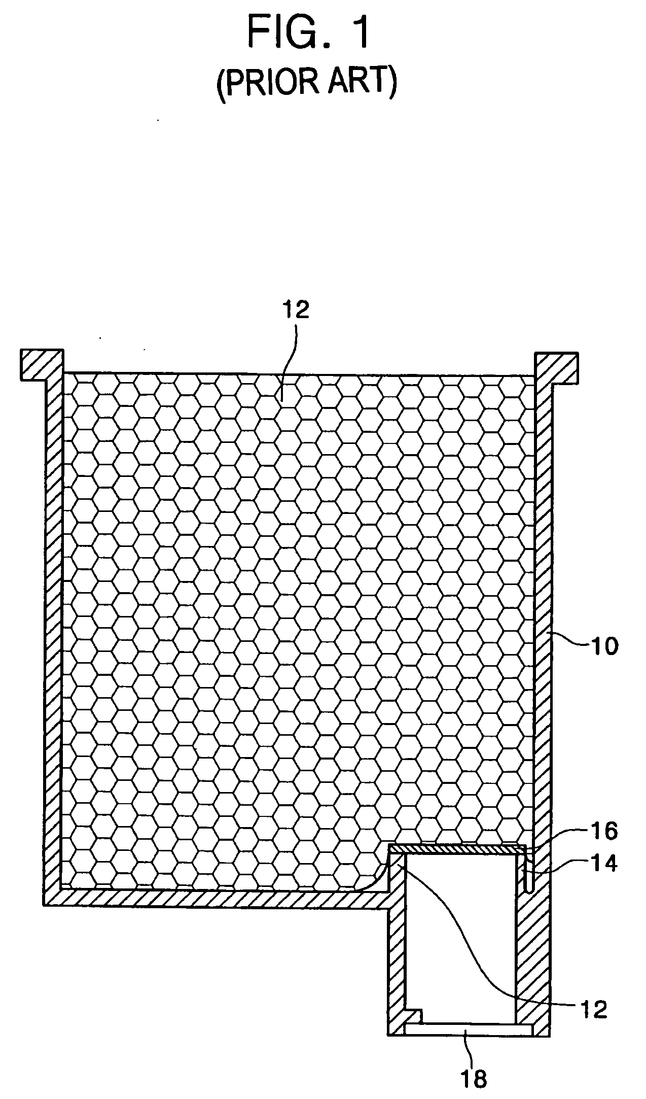
However, with regards to the wide array type printer head, a compression effect of foam is decreased at a portion where the ink pipe is not in contact with a partition to deteriorate supply performance and use efficiency of ink absorbed in the foam.
In addition, the filter attached to an upper end of the ink pipe and the partition is deformed at a portion adjacent to the partition, when the filter sags due to pressure applied by the foam, to deteriorate filter performance and decrease filter strength.
As a result, when a lid is attached to an upper portion of the ink cartridge by fusion bonding, fusion energy used to secure the lid to the ink cartridge may cause a portion of the filter to be separated from the upper end of the ink pipe and dust from the filter may block a nozzle formed at the printer head.

Method used


Image

  • Ink cartridge usable with a wide array type printer head
  • Ink cartridge usable with a wide array type printer head
  • Ink cartridge usable with a wide array type printer head

Examples


Embodiment Construction

[0034] Reference will now be made in detail to the embodiments of the present general inventive concept, examples of which are illustrated in the accompanying drawings, wherein like reference numerals refer to the like elements throughout. The embodiments are described below in order to explain the present general inventive concept by referring to the figures.

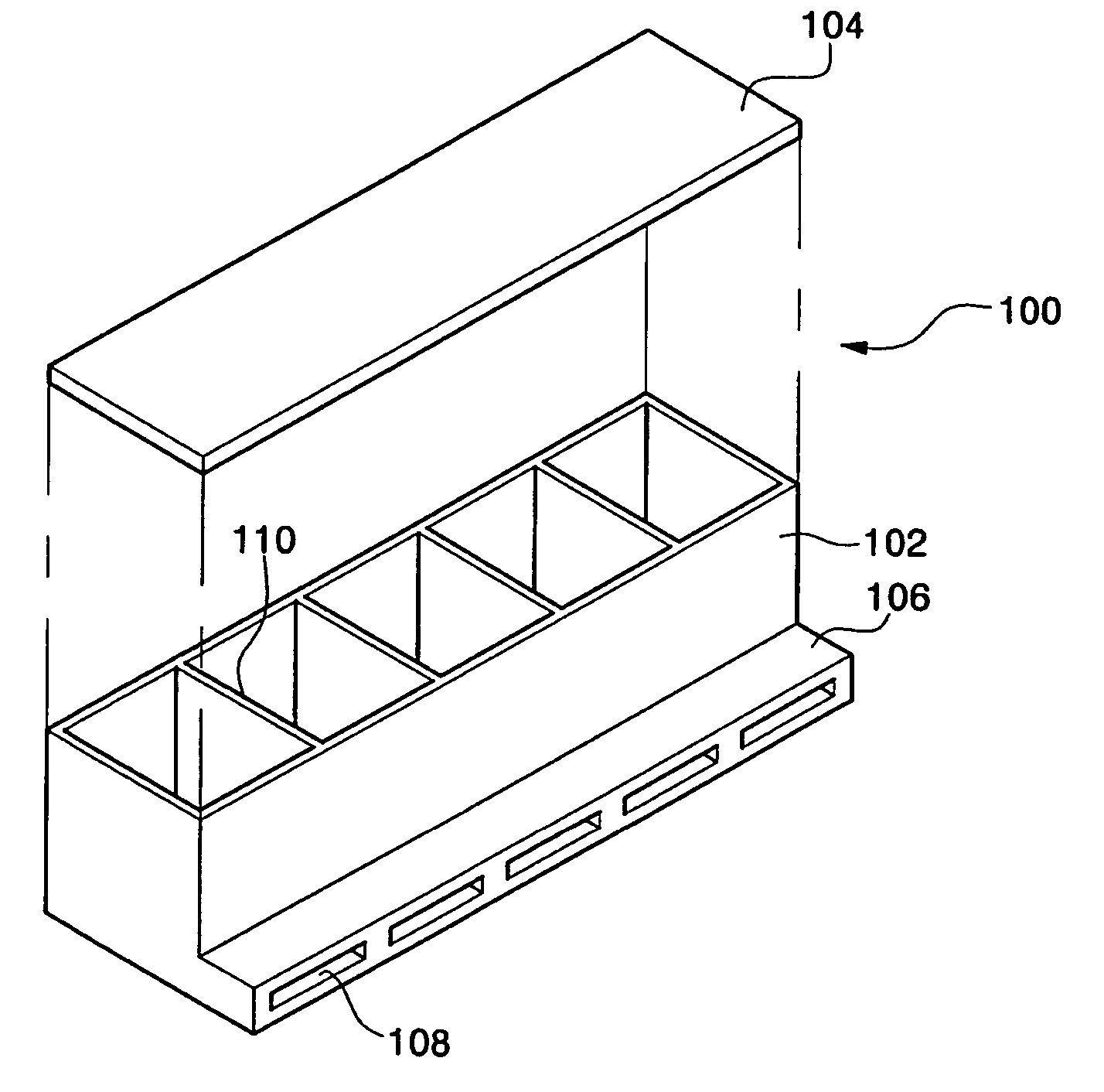
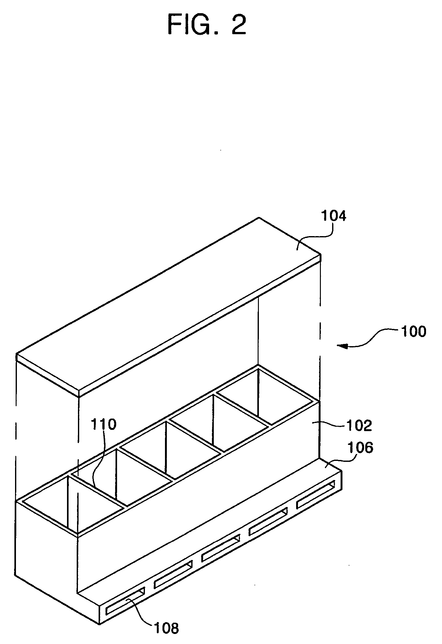
[0035] Referring to FIG. 2, a cartridge 100 according to an embodiment of the present general inventive concept is illustrated. The cartridge 100 includes a cartridge body 102 having a rectangular box shape and extending along a lateral length of a recording medium. In addition, the cartridge body 102 has an open upper part into which foam 12 (similar to FIG. 1) may be inserted. A lid 104 may be fusion-bonded to the upper part of the cartridge body 102 to seal an inner space of the cartridge body 102.

[0036] The inner space of the cartridge body 102 is divided into a plurality of small spaces by partitions 110. In the present ...


PUM


Abstract

An ink cartridge usable with a wide array type printer head includes: an ink cartridge body extending in a lateral direction of a recording medium and having an ink storage space, at least one ink pipe formed at a bottom surface of the ink cartridge body and having at least two inlet ports in fluid communication with the ink storage space, an ink channel in fluid communication with a bottom surface of the at least one ink pipe, and at least one ink discharge port in fluid communication with the ink channel to supply the ink to a printer head. The ink cartridge is capable of increasing ink supply performance and use efficiency of ink absorbed in foam disposed in the ink cartridge body by increasing a local compression of the foam by forming a plurality of ink pipes having a cross-sectional area that is less than or equal to than a cross sectional area of a conventional ink pipe. In addition, the ink cartridge is capable of preventing air from being trapped in the foam by the increase in the local compression in the foam.

Description

CROSS-REFERENCE TO RELATED APPLICATIONS [0001] This application claims the benefit of Korean Patent Application No. 2004-82363, filed Oct. 14, 2004, the disclosure of which is hereby incorporated herein by reference in its entirety. BACKGROUND OF THE INVENTION [0002] 1. Field of the Invention [0003] The present general inventive concept relates to an ink cartridge usable with a wide array type printer head and, more particularly, to an ink cartridge to effectively supply ink to a wide array type printer head capable of simultaneously ejecting the ink over an entire lateral line of a recording medium. [0004] 2. Description of the Related Art [0005] An inkjet printer is a device for performing a printing operation by ejecting fine ink droplets to a surface of a recording medium to form a desired shape. The inkjet printer uses an ink cartridge for storing and ejecting the ink. In general, the ink cartridge has a storage space for storing the ink therein, and a head chip for ejecting th...

Claims


Application Information

Patent Timeline
IPC IPC(8): B41J2/175
CPCB41J2/17513B41J2/155B41J2/17563B41J2/165
Inventor LEE, YOUNG-SU
Owner SAMSUNG ELECTRONICS CO LTD
Learn More