
Oral appliance

a technology for oral appliances and mouths, applied in the field of oral appliances, can solve the problems of reducing the uptake of such appliances in the market place, limiting the ability of trainers to reposition users' teeth, and high cost of producing such appliances, and achieve the effect of resisting delamination in us

Inactive Publication Date: 2006-04-20
FARRELL CHRISTOPHER JOHN
View PDF10 Cites 226 Cited by
  • Summary
  • Abstract
  • Description
  • Claims
  • Application Information

AI Technical Summary

Benefits of technology

[0025] The base member may also be regarded as being stiff and resist being deformed when a force is applied thereto. The resilience causes it to return to its original shape when the force is removed.
[0076] The thickening of the teeth engaging member may resemble an inverted aerofoil, e.g. with a curved lower surface and a substantially planar upper surface, when viewed in cross section. This shape of the web region of the teeth engaging member correctly positions the teeth of the upper and lower jaw relative to each other so as to encourage relaxation of the muscles and also the TMJ.

Problems solved by technology

However the limitation of custom made appliances is the high cost of producing such an appliance and this has reduced their uptake in the market place.
However because the trainer is soft it does not apply a strong retaining and correcting force to teeth that are received within the channels.
The softness of the silicone rubber material that abuts the teeth really limits the ability of the trainer to reposition a user's teeth.
However the polyurethane would be hard against the soft gums of the user and cause pain and discomfort.
In addition if the appliance was made of a single hard material it would have limited ability to bend and deform to receive misaligned teeth.
It would thus be harder to fit to a wide number of users all with their own individual arch sizes and teeth alignments.
Thus there would be difficulties in fitting the trainer in the first place.

Method used


Image

  • Oral appliance
  • Oral appliance
  • Oral appliance

Examples


Embodiment Construction

[0092] An oral appliance that is an orthodontic trainer or a sports guard in accordance with this invention may manifest itself in a variety of forms. It will be convenient to hereinafter provide a detailed description of some embodiments of the invention with reference to the accompanying drawings. The purpose of providing this detailed description is to instruct persons having an interest in the subject matter of the invention how to put the invention into practice. It is to be clearly understood however that the specific nature of this detailed description does not supersede the generality of the preceding statements. In the drawings:

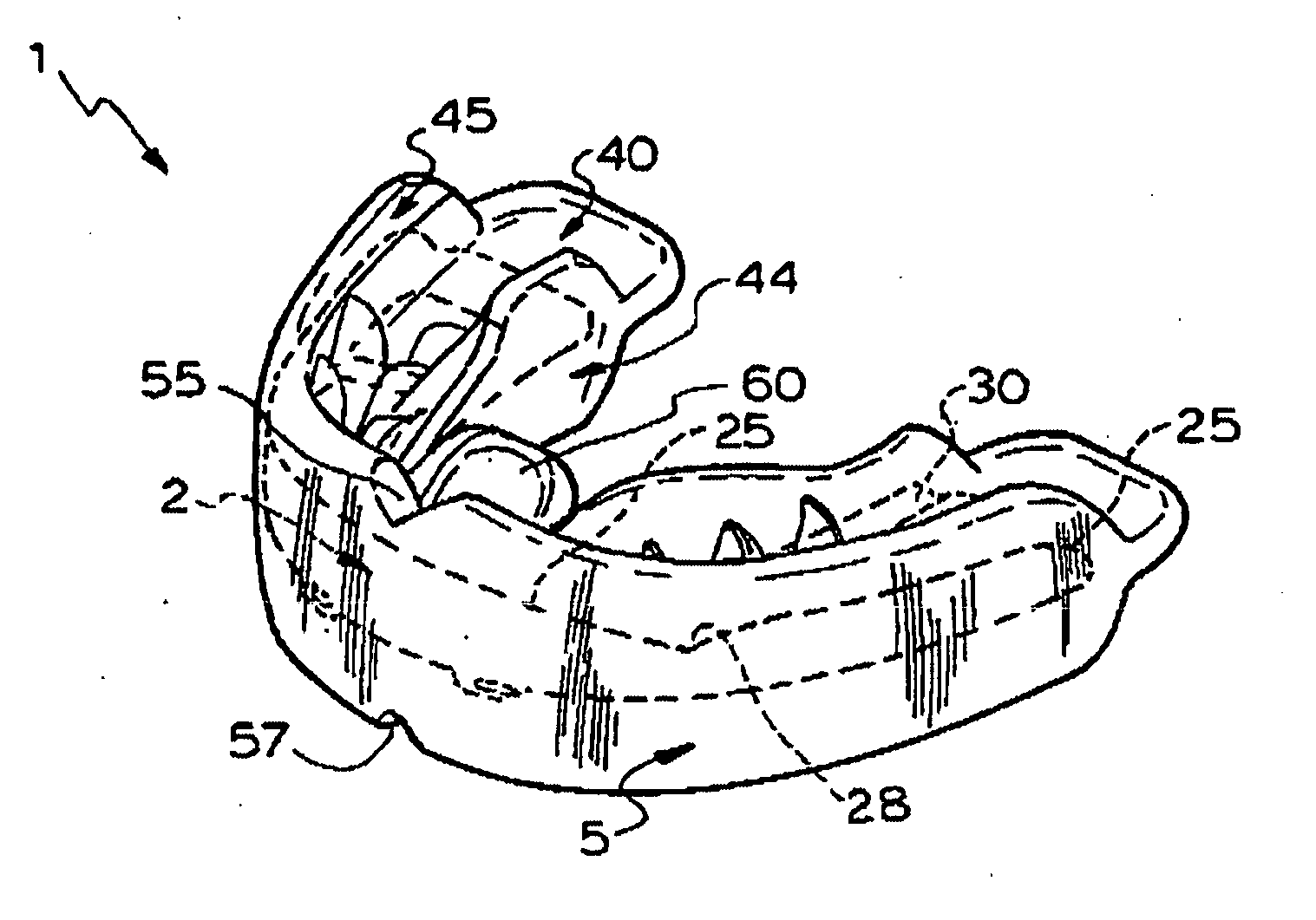
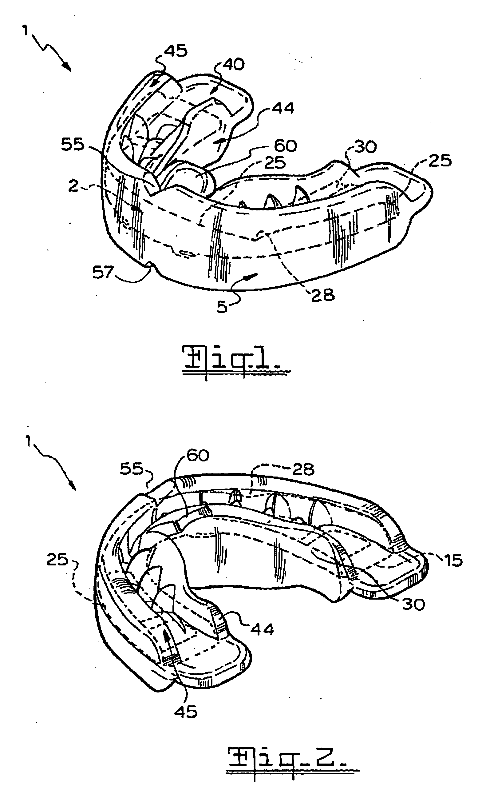
[0093]FIG. 1 is an upper front three dimensional view of an appliance that is an orthodontic trainer in accordance with the invention;

[0094]FIG. 2 is an upper rear three dimensional view of the appliance of FIG. 1;

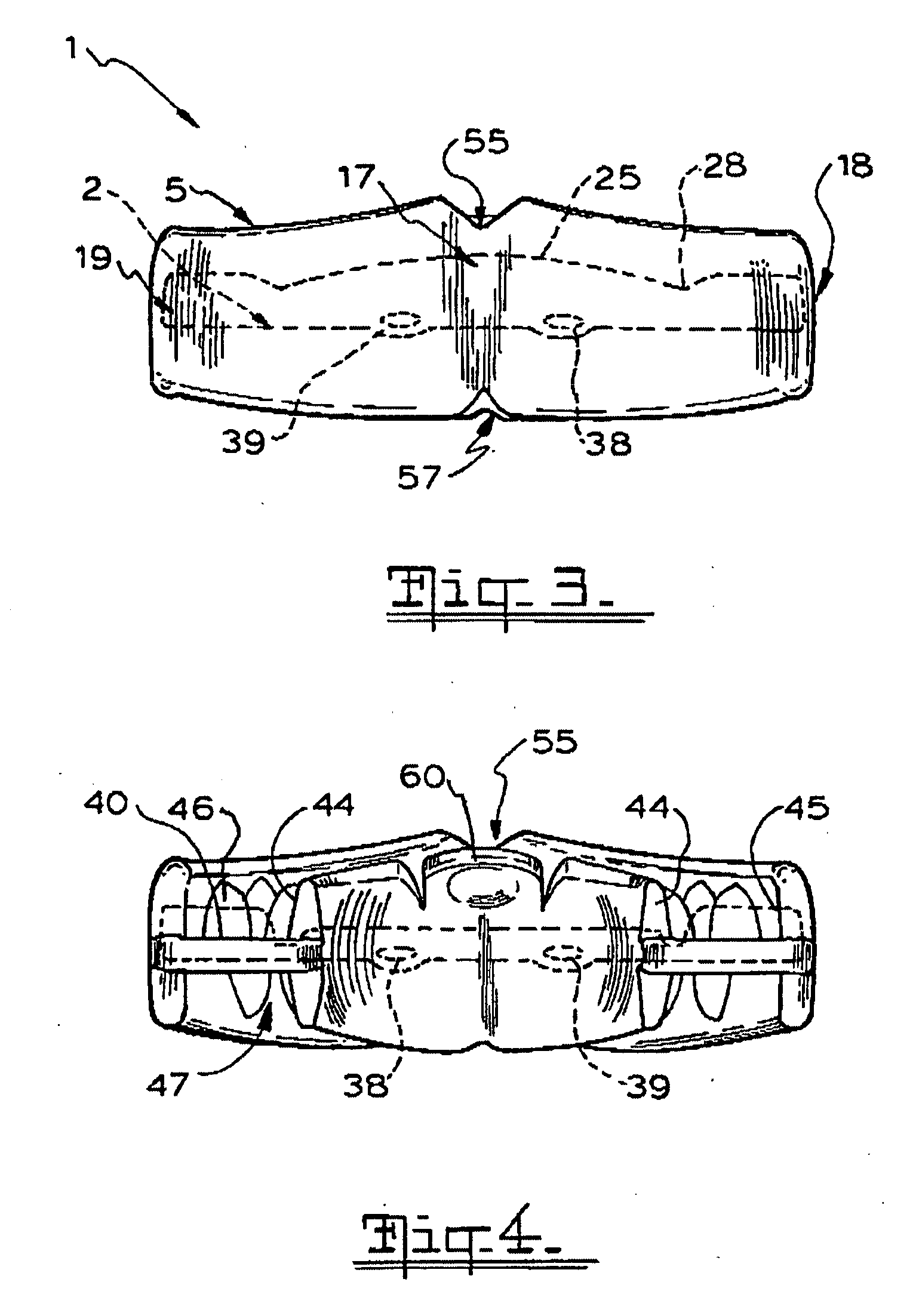
[0095]FIG. 3 is a front view of the appliance of FIG. 1;

[0096]FIG. 4 is a rear view of the appliance of FIG. 1;

[0097]FIG. 5 is a top ...


PUM


Abstract

An orthodontic trainer 1 for assisting the correction of the misalignment of teeth is disclosed. The trainer 1 comprises a base member 2 made of nylon having a generally U-shaped form corresponding to the outline of the jaw of a user and a teeth engaging member 5 that encases the base member 2. The base member 2 has an open frame structure with curved inner and outer elongate frame members 12, 10 interconnected at spaced intervals by transverse frame members 15. The trainer 1 includes a outer teeth repositioning formation in the form of an outer flange is positioned on the outer elongate frame member 10. The trainer 1 also includes an inner teeth repositioning formation on the inner elongate frame member 12. The continuous teething engaging member 5 that is made of silicone rubber or PVC comprises a web 40 and inner and outer flanges 44, 45 projecting up and down from both upper and lower faces of the web 40. These flanges 44, 45 and the web 40 define upper and lower channels within which the upper and lower teeth of the user can be received. The trainer 1 also includes teeth positioning formations on the teeth engaging member 5 projecting into the upper and lower channels for encouraging the correct positioning of the teeth of a user.

Description

FIELD OF THE INVENTION [0001] This invention relates to an oral appliance. [0002] This invention relates particularly but not exclusively to an oral appliance that is an orthodontic appliance used to assist in correcting the misalignment of teeth by applying a correcting force to the teeth. It will therefore be convenient to hereinafter describe this invention in detail with reference to this example application. However it is to be clearly understood that the invention is capable of broader application. For example the invention might be applied to appliances that encourage an improvement in oral habits such as tongue thrusting without applying a repositioning force to the teeth. [0003] Finally the appliance could also be used as a mouth guard or sports guard as well. DEFINITIONS [0004] In this specification the term engaging shall bear a broad meaning and shall not be limited to mean retaining or latching engagement. BACKGROUND TO THE INVENTION [0005] Various types of orthodontic ...

Claims


Application Information

Patent Timeline
Patent Type & Authority Applications(United States)
IPC IPC(8): A61C3/00
CPCA61C7/08A63B71/085A63B2071/086
Inventor FARRELL, CHRISTOPHER JOHN
Owner FARRELL CHRISTOPHER JOHN
Learn More