
Dual coated cast iron brake rotor and method of construction

a brake rotor and cast iron technology, applied in the field of brake rotors, can solve the problems of increased layer thickness on the outer surface of the brake rotor, reduced friction coefficient, and easy corrosion of cast iron, and achieves long and useful life, long service life, and economic effect in manufacture and us

Inactive Publication Date: 2009-01-29
FEDERAL MOGUL WORLD WIDE
View PDF25 Cites 34 Cited by
  • Summary
  • Abstract
  • Description
  • Claims
  • Application Information

AI Technical Summary

Benefits of technology

"The invention is a brake rotor for a vehicle that has a ceramic anti-wear coating for braking and a corrosion-resistant coating for non-braking surfaces. The rotor also has a nickel-based intermediate layer and can be made economical and environmentally friendly. The technical effects of the invention include resistance to wear, corrosion, and long life of the brake rotor."

Problems solved by technology

However, cast iron is susceptible to corrosion when exposed to moisture and other chemicals encountered from ground surfaces, such as road salt, for example.
The ensuing corrosion layer results in a reduced coefficient of friction and increased layer thickness on the outer surface of the brake rotor.
As such, interference between the corrosion layer and an adjacent brake pad can result, thereby causing undesirable feedback through the brake system to the driver, and noise.
Although the anticorrosion coating can be effective to initially reduce corrosion, they are typically not well suited to provide wear protection.
In addition, anti-wear coatings typically have a reduced melt point temperature, and thus, can result in unwanted asperities beneath a brake pad, thereby producing unwanted vibration, noise and wear in use.

Method used


Image

  • Dual coated cast iron brake rotor and method of construction
  • Dual coated cast iron brake rotor and method of construction
  • Dual coated cast iron brake rotor and method of construction

Examples


Embodiment Construction

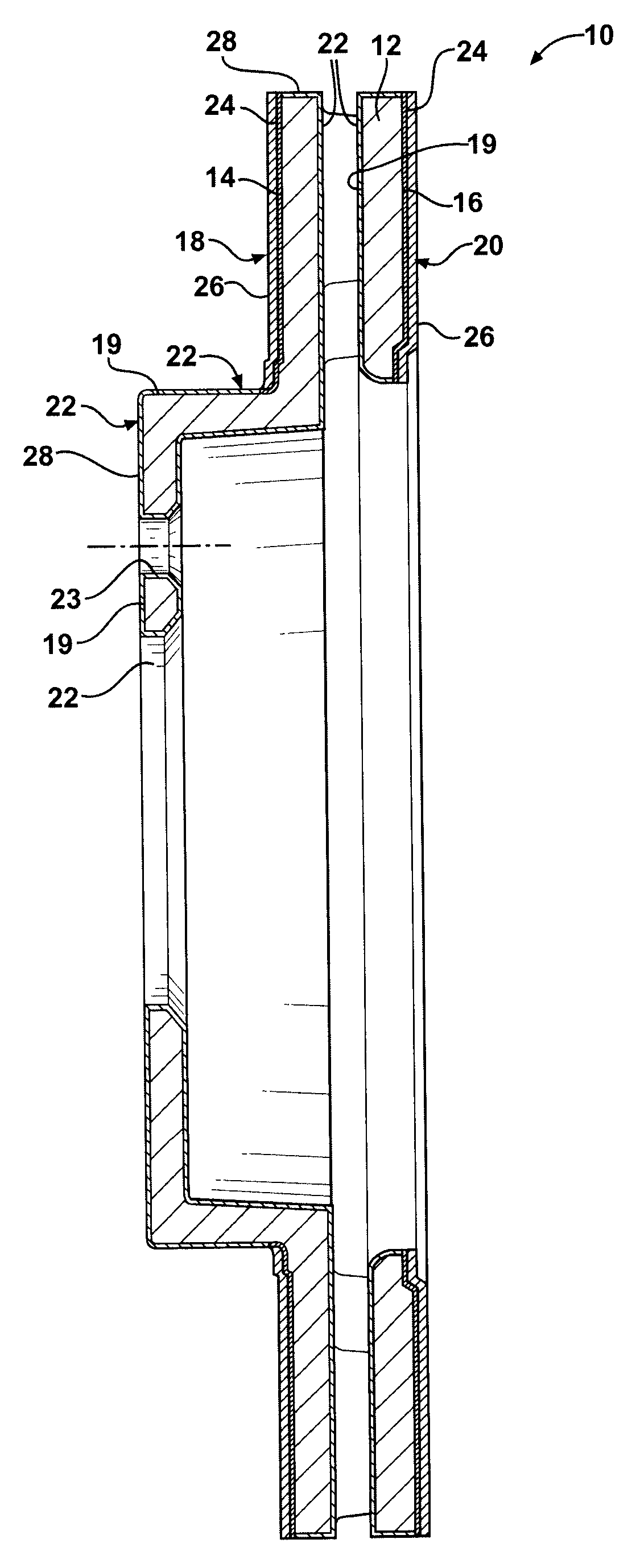
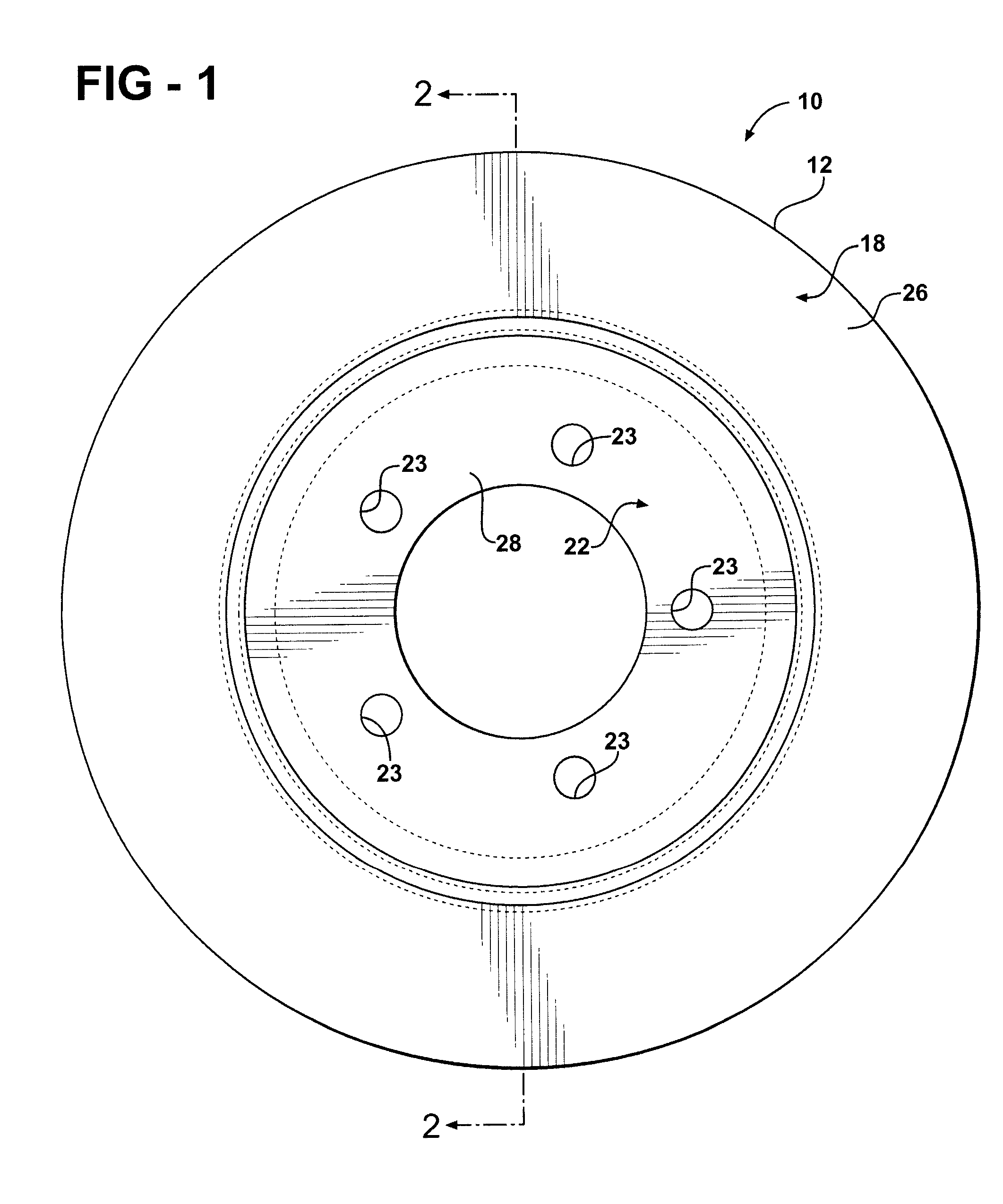
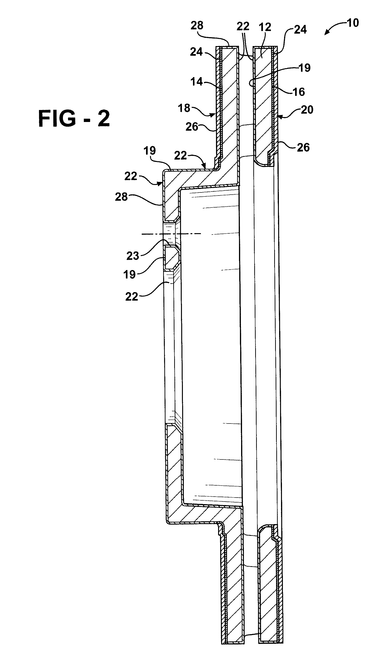
[0014]Referring in more detail to the drawings, FIGS. 1 and 2 illustrate a cast iron brake rotor 10 constructed according to one presently preferred embodiment of the invention. The brake rotor 10 is constructed from a cast iron disc 12 having opposite sides 14, 16 (FIG. 2) with annular friction surfaces 18, 20 providing braking engagement with opposed brake pads (not shown). Other than the friction surfaces, 18, 20, the rotor 10 also has non-braking surfaces 22 spaced from the braking friction surfaces 18, 20 that do not come into contact with the brake pads during braking. The friction surfaces 18, 20 are constructed to resist wear, and the non-braking surfaces 22 are protected constructed to resist corrosion. Accordingly, the useful life of the brake rotor 10 is enhanced.

[0015]In constructing the brake rotor 10, the opposite sides 14, 16 of the disc 12 are machined to the general size and shape of the finished brake rotor, wherein bolt openings 23 are formed, and the sides 14, 16...


PUM

PropertyMeasurementUnit
thicknessaaaaaaaaaa
thicknessaaaaaaaaaa
thicknessaaaaaaaaaa

Abstract

A brake rotor for a vehicle and method of construction thereof provides a cast iron disc with a first coating of a ceramic anti-wear material adhered to the cast iron disc to provide an annular friction surface for braking engagement with a brake pad. The disc has a second coating different from the first coating. The second coating is adhered to the disc to provide an annular non-braking surface spaced from the friction surface. The non-braking surface provided by the second coating is resistant to corrosion.

Description

BACKGROUND OF THE INVENTION[0001]1. Technical Field[0002]This invention relates generally to brake rotors, and more particularly to cast iron brake rotors.[0003]2. Related Art[0004]Cast iron brake rotors are used widely on vehicles for several reasons, including relatively low cost, relatively high thermal conductivity, its ability to be readily machined, and its ability to resist cracking in use. However, cast iron is susceptible to corrosion when exposed to moisture and other chemicals encountered from ground surfaces, such as road salt, for example. The ensuing corrosion layer results in a reduced coefficient of friction and increased layer thickness on the outer surface of the brake rotor. As such, interference between the corrosion layer and an adjacent brake pad can result, thereby causing undesirable feedback through the brake system to the driver, and noise.[0005]In order to overcome the problems associated with corrosion, corrosion resistant coatings have been applied to br...

Claims


Application Information

Patent Timeline
Patent Type & Authority Applications(United States)
IPC IPC(8): F16D65/12B23P17/00
CPCF16D65/127F16D2200/0013Y10T29/49982F16D2250/0046F16D2200/0039
Inventor HAMPTON, KEITH
Owner FEDERAL MOGUL WORLD WIDE
Learn More