Electrostatic spraying system

a spraying system and electrostatic technology, applied in the direction of electrostatic heating/cooling, electrostatic spraying apparatus, engine components, etc., can solve the problems of galling inside the forming dye of the machine, unfavorable dark marks on the edges, and devices that do not permit adjustment or reliable consistency of wax, etc., to achieve more uniform and efficient application of hot mel

Active Publication Date: 2019-12-17
SPRAYING SYST
View PDF7 Cites 0 Cited by
  • Summary
  • Abstract
  • Description
  • Claims
  • Application Information

AI Technical Summary

Benefits of technology

[0004]It is an object of the present invention to provide a spraying system for more uniformly and efficiently applying hot melt waxes, oils, or other lubricants to metal parts or the like.
[0008]Still a further object is to provide such an electrostatic spraying system that is relatively simple in construction and which lends itself to economical manufacture and usage.

Problems solved by technology

This creates undesirable dark marks on the edges of the can.
Such devices also do not permit adjustability or reliable consistency in wax application in high speed canning operations.
Under or uneven lubricating can cause galling inside the forming dyes of the machine.
Once the dye is galled in such manner it can cause denting, dinging, or scratching in the subsequently processed cans.
Over lubricating, particularly on the inside of the cans, may result in contamination of the beverage product itself.
Since can necking machines operate at speeds as high as 3000 cans per minute, any such defects in the wax application can cause rejection and scrapping of large batches of cans.

Method used


Image

  • Electrostatic spraying system
  • Electrostatic spraying system
  • Electrostatic spraying system

Examples


Embodiment Construction

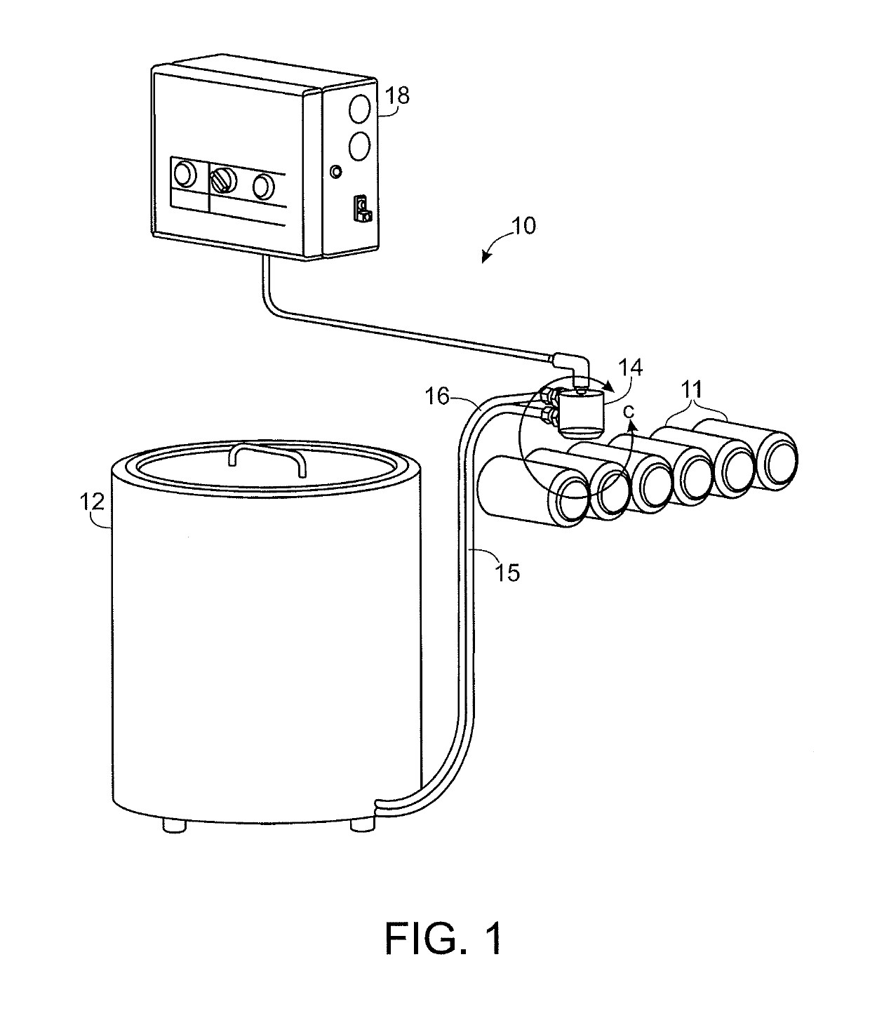
[0016]Referring now more particularly to the drawings, there is shown an illustrative lubricant dispensing system 10 in accordance with the invention. The illustrated lubricant dispensing system 10 is shown for use in applying hot melt wax to the end perimeters of beverage cans 11, such as during processing through a high speed can necking machine. The lubricant dispensing system 10 in this case includes a heated tank or reservoir 12 with an internal pumping system for containing a quantity of lubricant such as wax in a heated state, an electrostatic spray head 14 coupled to the tank 12 by supply and return conduits 15, 16 respectively, and a control 18 for controlling power to the electrostatic spray head 14. As will be understood by persons skilled in the art, in can necking machines, beverage cans are simultaneously rotated as they are conveyed past a coating station where a small quantity of lubricant is applied to the end perimeters of the cans. As will be appreciated by those ...


PUM


Abstract

A lubricant dispensing system having particular utility for applying a tightly controlled thin line of lubricant about the perimeter of cans as they are processed. The lubricant dispensing system includes an electrostatic spray head having a nozzle body that defines a lubricant receiving chamber for electrically charging lubricant therein and a capillary tube supported by the nozzle body having an inlet end communicating with the lubricant receiving chamber and an outlet that defines a discharge orifice of the electrostatic spray head. The capillary tube has a diameter between about 0.2 and 0.3 inches for directing electrostatically charged lubricant onto an item to be lubricated in a controlled thin line having a width no greater than 0.125 inches. The electrode is adjustably positionable relative to the capillary tube for selectively controlling the rate of discharging lubricant, and the electrode is configured for enhancing electrostatic charging of lubricant through the capillary tube.

Description

CROSS-REFERENCE TO RELATED APPLICATIONS[0001]This patent application claims the benefit of U.S. Provisional Patent Application No. 62 / 015,113, filed Jun. 20, 2014, which is incorporated by reference.FIELD OF THE INVENTION[0002]The present invention relates generally to spraying systems, and more particularly to an electrostatic spraying system for applying hot melt waxes, oils, greases, or other lubricants onto metal parts or the like. The invention has particular application to systems for applying hot melt waxes to cans in beverage can necking machines.BACKGROUND OF THE INVENTION[0003]In beverage can necking machines, it is necessary that a lubricant such as wax be applied to the top rough edge of a can prior to the can entering the can necking machine in order to lubricate forming dyes of the machine. The wax must be applied in a fine line of about no more than 0.125 inches from the top of the can and should not wrap around the inside of the can. It is known to use roller applica...

Claims


Application Information

Patent Timeline
Patent Type & Authority Patents(United States)
IPC IPC(8): B05B5/025B05B5/00B05B15/58F16N7/12B05B1/30B05B1/02
CPCB05B15/58B05B1/304B05B5/001B05B5/025B05B1/02F16N7/12F16N7/06
Inventor ACKERMAN, THOMAS E.HUFFMAN, DAVID C.ST. PETER, GLENN R.
Owner SPRAYING SYST
Why Eureka
Try Eureka