LED ink curing apparatus

a curing apparatus and led ink technology, applied in the direction of lighting and heating apparatus, lighting heating/cooling arrangements, drying, etc., can solve the problems of reducing the life of leds, affecting the efficiency of print curing, and existing cooling methods are problematic, so as to achieve uniform cooling

Inactive Publication Date: 2016-07-21
GEWEC
View PDF4 Cites 1 Cited by
  • Summary
  • Abstract
  • Description
  • Claims
  • Application Information

AI Technical Summary

Benefits of technology

[0008]It has been found that having a fluid jet “directed towards” the or each heat sink significantly improves the cooling of an LED print curing apparatus. Furthermore, by using jets that are directed the flow and pressure of the fluid, such as water, onto the heat sink can be carefully controlled to achieve highly efficient transfer of heat from the heat sink and also cooling uniformity along the length of the print curing apparatus. The present invention provides cooling that is length independent, wherein the length of the apparatus is understood to be the longest dimension of the apparatus. The present applicant has found that the flow rates that would be required by existing “flow past” devices to achieve the cooling effect of the present invention would be significantly greater than those required by the present invention.
[0009]It is understood that the “jet” of the present invention is a forceful stream of fluid discharged from a narrow aperture and is “directed towards” the heat sink; that is, the fluid jet is caused to move in a particular, controlled way. The fluid jet “directed towards” the heat sink is controlled to achieve the desired cooling effect; for example, any one or more of the speed, direction, volume, pressure and / or shape of the fluid jet is regulated / aimed to achieve the highly efficient and uniform cooling.
[0021]It is envisaged that the spacing of the fluid jets can be pre-determined according to the heat profile along the heat sink—i.e. along the longer dimension of the heat sink / s and / or the print curing apparatus, and also across the heat sink—i.e. along the shorter dimension of the heat sink / s and / or the print curing apparatus. This enables the temperature of the heat sink to be carefully controlled to achieve uniform cooling.

Problems solved by technology

Inefficient cooling of the LEDs significantly reduces the lifetime of the LEDs.
However, it has been found that existing cooling methods are problematic because the cooling achieved is not sufficiently effective nor is cooling uniform along the length of the apparatus.
Thus, the efficiency of the print curing varies along the length of the apparatus to the detriment of the quality of curing along the substrate to be cured.

Method used


Image

  • LED ink curing apparatus
  • LED ink curing apparatus
  • LED ink curing apparatus

Examples


Embodiment Construction

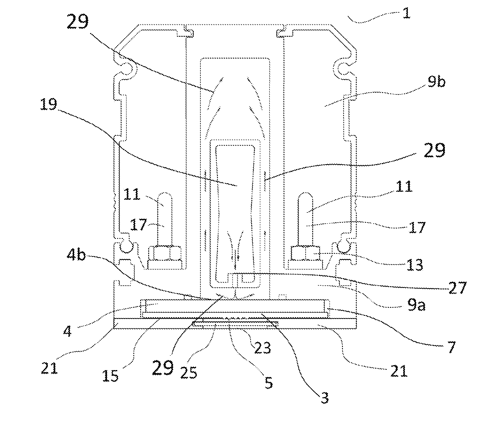
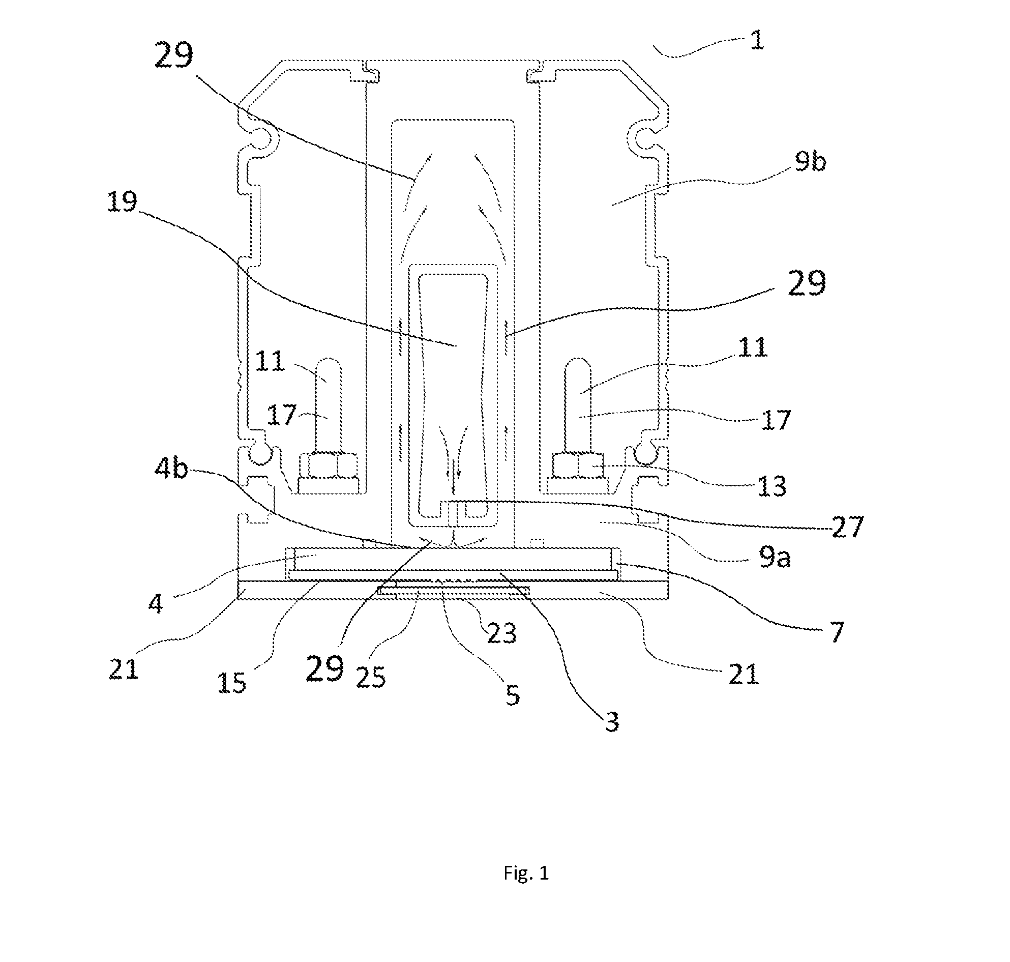
[0040]Referring to FIG. 1, there is shown a UV print curing apparatus 1 comprising a plurality of LED modules 3. Each LED module 3 comprises a plurality of LEDs 5. A heat sink 4 is provided adjacent to a LED mounting area 7. The heat sink 4 is a copper plate insert supported by a plastic or aluminium plate or frame. The heat sink 4 is provided above the LED modules 3; that is, on the opposing face of the mounting area 7 to the substrate (not shown). The copper plate insert of the heat sink 4 is used to increase the conductivity of heat carried away from the LED modules 3.

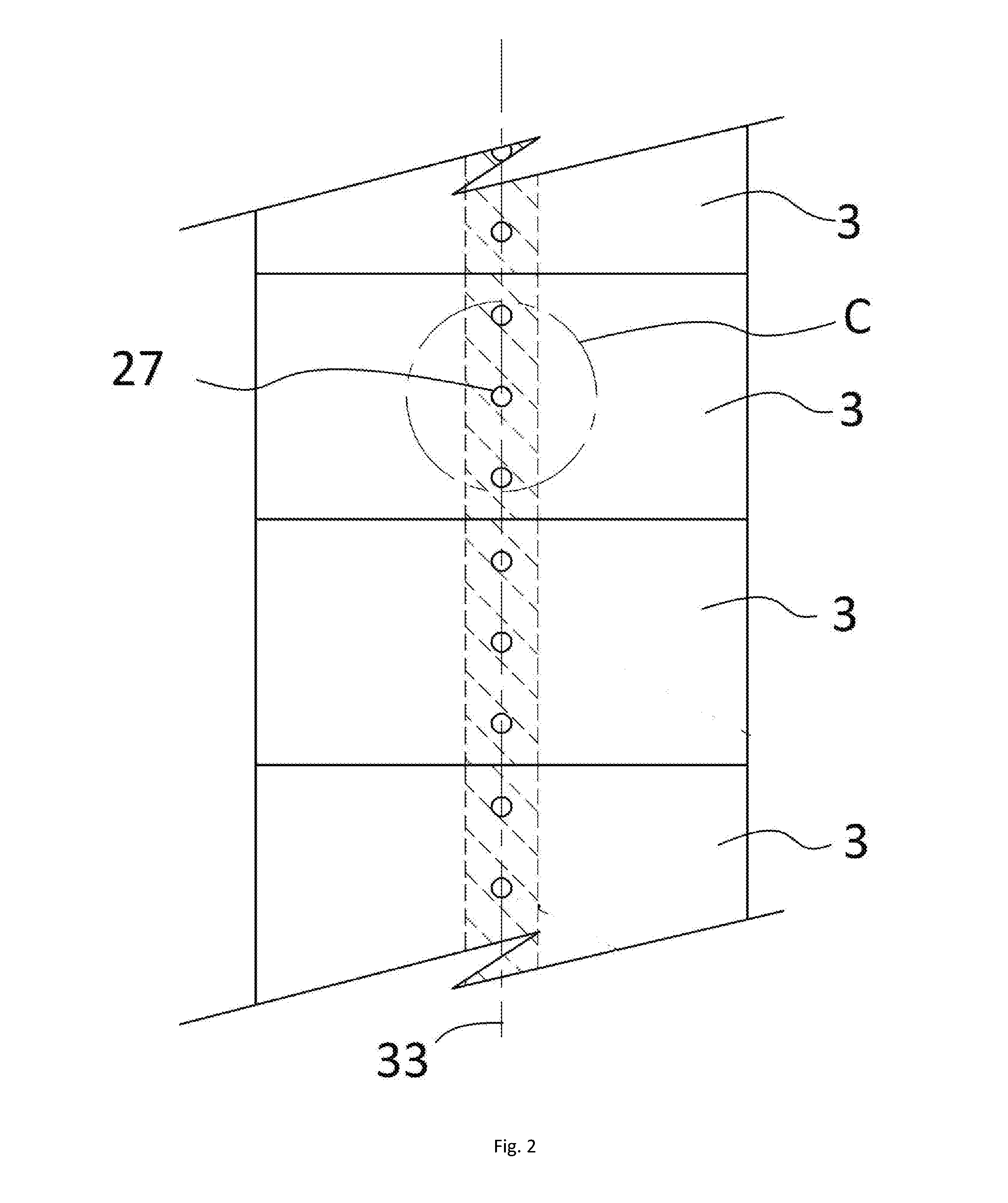
[0041]Referring to FIG. 1 and FIG. 2, multiple LED modules 3 are mounted side-by-side along the length of the print curing apparatus 1. The arrangement of LEDs 5 in each module 3 and the grouping of the multiple LED modules 3 in an array is configured according to the print effect to be achieved by the UV print curing apparatus 1. For example, each LED module 3 includes a plurality of LEDs 5 grouped across a central...


PUM


Abstract

A print curing apparatus (1) comprising one or more LED modules (3) wherein each LED module (3) comprises at least one LED (5) and wherein the or each LED module (3) is mounted on a heat sink (4); and a cooling system (19) comprising one or more fluid jets (29) wherein the or each fluid jet (29) is directed towards the or each heat sink (4).

Description

FIELD OF THE INVENTION[0001]The present invention relates to a print curing apparatus, having an LED array.BACKGROUND OF THE INVENTION[0002]The use of ultra violet (UV) LED (light-emitting diode) arrays for ink curing is becoming increasingly popular as an alternative to traditional mercury arc UV lamps. The ink curing apparatus must be cooled effectively to reduce the risk of apparatus failure and also to reduce any safety risks associated with overheating of the apparatus. Effective cooling of LED print curing apparatus also ensures maximum efficiency of print curing, whilst minimising the cost and environmental impact of the use of the print curing apparatus. Furthermore, effective cooling ensures that the lifetime of the valuable LED units is as long as possible and reduces the time, cost and inconvenience of maintenance of the apparatus. Inefficient cooling of the LEDs significantly reduces the lifetime of the LEDs.[0003]Patent publications US 2008 / 151029 and WO 2010 / 105365 dis...

Claims


Application Information

Patent Timeline
Patent Type & Authority Applications(United States)
IPC IPC(8): G21K5/00F21V29/89F21V29/60F21V29/70F21V29/58
CPCG21K5/00F21V29/70F21Y2101/02F21V29/60F21V29/89F21V29/59B41F23/0409B41F23/0453F26B3/28B41J11/00214
Inventor RAE, MALCOLMHICKS, JAMESRAE, ROBERT
Owner GEWEC
Why Eureka
Try Eureka