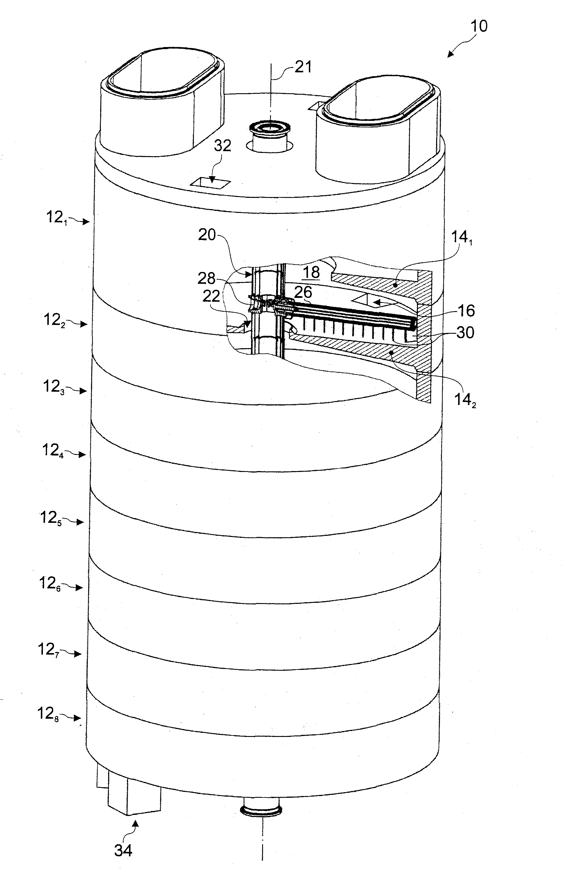
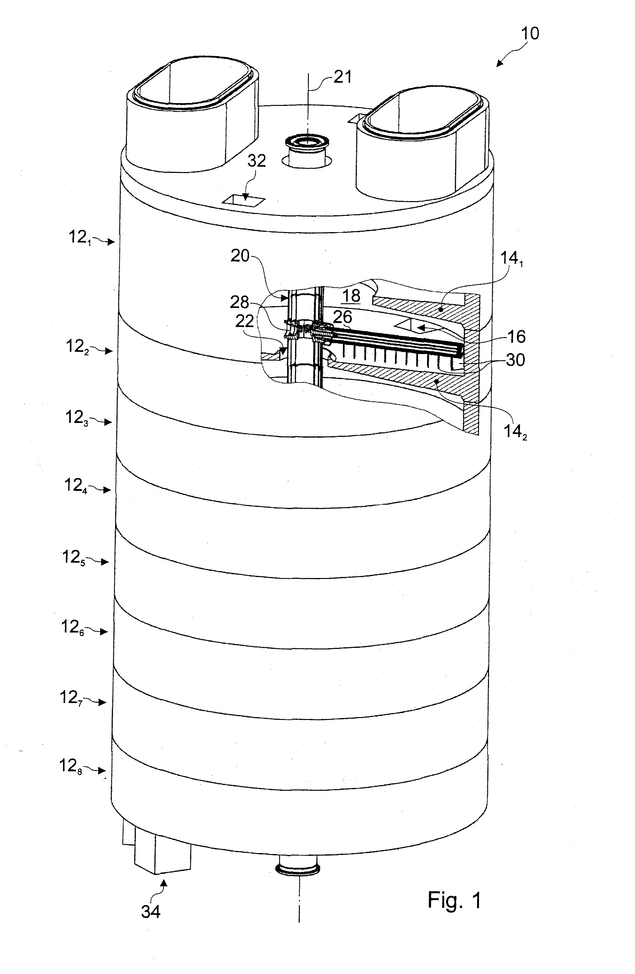
[0011]More particularly, the present invention proposes a multiple hearth furnace comprising, in a manner known per se: a plurality of hearth chambers arranged one on top of the other; a hollow vertical rotary shaft extending centrally through the hearth chambers and including an outer shell; in each of the hearth chambers, at least one rabble arm secured to the shaft; a gas cooling system for the shaft and the rabble arms including, within the outer shell, an annular main distribution channel for supplying a cooling gas to the rabble arms and a central exhaust channel for evacuating the cooling gas leaving the rabble arms; and a connecting means for connecting the rabble arms to the shaft including cooling
gas supply means in
direct communication with the annular main distribution channel and cooling gas return means in
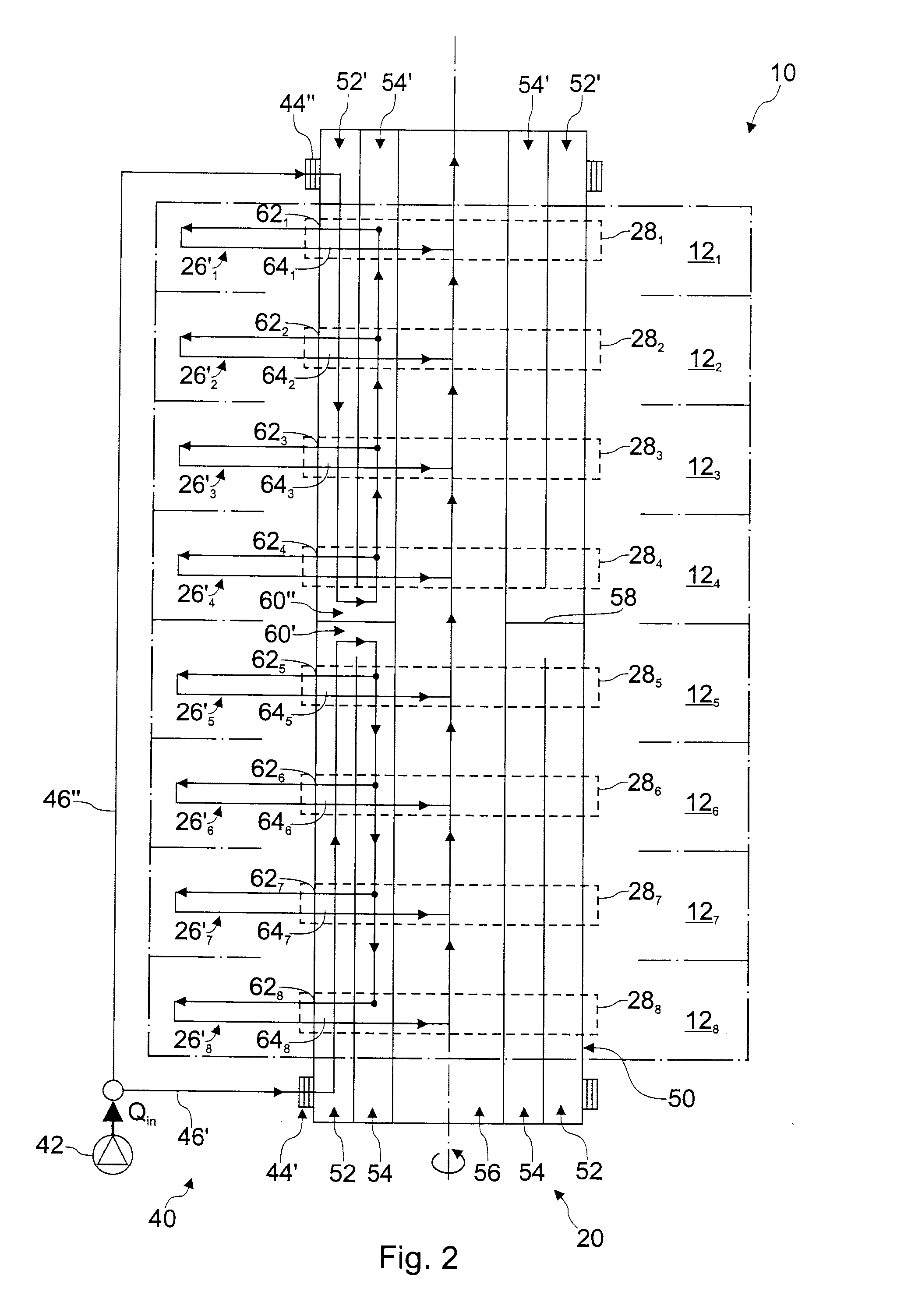
direct communication with the central exhaust channel. In accordance with the present invention, the gas cooling system further comprises an annular main supply channel surrounding the annular main distribution channel and being outwardly delimited by the outer shell. A cooling gas inlet is connected to the annular main supply channel. A cooling gas passage between the annular main supply channel and the annular main distribution channel is spaced from the cooling gas inlet, so that cooling gas supplied to the cooling gas inlet has to flow through the annular main supply channel through several hearth chambers before it flows through the cooling gas passage into the annular main distribution channel. It will be appreciated that with such a system, the whole main supply flow of cooling gas is first used to provide an efficient and uniform cooling of the outer shell of the vertical rotary shaft in several hearth chambers. The constant, high flow rate in the annular main supply channel warrants a relatively small temperature increase of the cooling gas between the cooling gas inlet and the cooling gas passage in the annular main distribution channel. In this inner annular distribution channel, the flow of the cooling gas—which now diminishes from hearth chamber to hearth chamber—is relatively well protected against additional
warming up, so that the rabble arms in all superposed hearth chambers are supplied with a cooling gas at substantially the same temperature. All this results in a very efficient and uniform cooling of the shaft and the rabble arms.
[0012]The gas cooling system can e.g. comprise a single cooling gas inlet connected either to the lower or to the upper end of the vertical rotary shaft, i.e. the cooling gas supplied to the cooling gas inlet has to flow through the annular main supply channel through all hearth chambers before it flows through the cooling gas passage into the annular main distribution channel. However, in a preferred embodiment, the gas cooling system further comprises partition means partitioning the annular main supply channel and the annular main distribution channel in a
lower half and an upper half. A lower cooling gas inlet is then connected to the
lower half of the annular main supply channel at the lower end of the shaft, and an upper cooling gas inlet is connected to the upper half of the annular main supply channel at the upper end of the shaft. A lower cooling gas passage is arranged between the
lower half of the annular main supply channel and the lower half of the annular main distribution channel and located near the partition means, so that cooling gas supplied to the lower cooling gas inlet has to flow upwards though the lower half of the annular main supply channel up to the partition means before it can flow through the lower cooling gas passage into the lower half of the annular main distribution channel. An upper cooling gas passage is arranged between the upper half of the annular main supply channel and the upper half of the annular main distribution channel and located near the partition means, so that cooling gas supplied to the upper cooling gas inlet has to flow downwards though the upper half of the annular main supply channel down to the partition means before it can flow through the second cooling gas passage into the upper half of the annular main distribution channel. It will be appreciated that this system results in a further improvement of the cooling system of the shaft and the rabble arms. With this split system, it is e.g. easier to equilibrate
gas supply for the rabble arms in the superposed hearth chambers.
[0013]A preferred embodiment of the outer shell comprises: shaft support tubes and cast rabble arm fixing nodes interconnecting the shaft support tubes, wherein at least one rabble is fixed to each of the rabble arm fixing nodes. In this shaft, the rabble arm fixing node and the shaft support tubes are advantageously welded together. The shaft support tubes are advantageously made of thick walled stainless steel tubes and are dimensioned as
structural load carrying members between the rabble arm fixing nodes. It will be appreciated that such a shaft can be easily manufactured at relatively low costs using standardized elements. It provides however a strong, long-lasting support structure that has a very good resistance with regard to temperature and corrosive agents in the hearth chambers.
[0016]A further preferred embodiment of a rabble arm fixing nodes comprises a ring-shaped cast body including: at least one socket for receiving therein the plug body of the rabble arm. A central passage forms the central exhaust channel for the cooling gas within the rabble arm fixing node. First secondary passages are arranged in a first ring section of the cast body, so as to provide gas passages for cooling gas flowing through the annular main distribution channel. Second secondary passages are arranged in a second ring section of the cast body, so as to provide gas passages for cooling gas flowing through the annular main supply channel. The cooling
gas supply means is arranged in the cast body so as to interconnect the annular internal supply channel for the cooling gas with at least one gas outlet opening within the socket and advantageously comprises at least one oblique bore extending through the ring-shaped cast body from the second ring section into a lateral surface delimiting the socket. The cooling gas return means is arranged in the cast body so as to interconnect the central passage with at least one gas inlet opening within the socket and advantageously comprises a through hole in axial extension of the socket. This embodiment of an arm fixing node combines a low pressure drop cooling gas distribution in the shaft and a
solid fixing of the rabble arm on the shaft with a very compact and cost saving design. With its integrated gas passages, it substantially contributes to the fact that the vertical rotary shaft, which includes three co-axial cooling channels therein, can be manufactured using a very small number of standardized elements. It also essentially contributes to warranting a strong, long-lasting shaft support structure with a very good resistance with regard to temperature and corrosive agents in the hearth chambers.
[0017]In a preferred embodiment, a section of the shaft extending between two adjacent hearth chambers comprises: a shaft support tube arranged between two arm fixing nodes to form the outer shell of the section of the shaft, the shaft support tube delimiting the annular main supply channel to the outside; an intermediate gas guiding jacket arranged within the shaft support tube so as to delimit the annular main supply channel to the inside and the annular main distribution channel to the outside; and an inner gas guiding jacket arranged within the intermediate gas guiding jacket so as to delimit the annular main distribution channel to the inside and the central exhaust channel to the outside. In this preferred embodiment, the intermediate gas guiding jacket advantageously comprises: a first tube section with a first end fixed to the first fixing node and a free second end; a second tube section with a first end fixed to the second fixing node and a free second end; a sealing means providing a sealed connection between the free second end of the first tube section and the free second end of the second tube section, while tolerating relative movement in the axial direction of both free second ends. Similarly, the inner gas guiding jacket advantageously comprises: a first tube section with a first end fixed to the first fixing node and a free second end; a second tube section with a first end fixed to the second fixing node and a free second end; a sealing means providing a sealed connection between the free second end of the first tube section and the free second end of the second tube section, while tolerating relative movement in the axial direction of both free second ends. The sealing means advantageously comprises a sealing sleeve fixed to the free second end of one of the first or second tube sections and engaging in a sealed manner the free second end of the other tube section. It will be appreciated that such a shaft section can be easily manufactured at relatively low costs using standardized elements.

