Multi-region twin-shaft cutting system

a cutting system and multi-region technology, applied in the field of multi-region twin-shaft cutting system, can solve the problems of high and today inappropriate amount of energy demand/energy expenditure for prior art comminuting, high proportion of unwanted oversize particles in the final product, and complicating the further processing and marketing of comminuted materials, so as to achieve significant more efficient effects

Active Publication Date: 2020-10-13
LINDNER RECYCLINGTECH
View PDF42 Cites 0 Cited by
  • Summary
  • Abstract
  • Description
  • Claims
  • Application Information

AI Technical Summary

Benefits of technology

[0015]The disk-like and / or plate-like and / or knife-like severing elements can have the shape of a rectangle, a parallelogram or a square. It is understood that the severing elements are typically fitted to the supporting elements such that the severing element is fitted approximately in its center to the supporting element which is perpendicular thereto. The leading edge region of the severing elements facing the gap during rotation of the shafts in opposite manner, also in short referred to as the leading edge, can with a cutting region suitably exert more pressure on a smaller area so that the efficiency of the operation, i.e. comminuting by cutting counter to the counter severing element can be increased.
[0023]This third severing process typically also occurs in a region between the two supporting elements of the other shaft. The material is thereafter, for example, during the same opposite rotation of the two shafts again comminuted, e.g. between the first separating element of the one shaft and the separating element of the other shaft. Where in particular the leading edge of the separating element of the one shaft operates counter to the edge facing away from the leading edge of the other separating element. This fourth separating process typically occurs in the discharge region of the system. The material can by combining the four separating processes be comminuted more efficiently and uniformly. A final product is created that is uniform in grain size and virtually free of undesirable oversize particles. The comminuting material can practically be directly marketed without further complicated subsequent techniques needing to be employed, such as screening. Furthermore, the energy demand for comminuting is greatly reduced due to uniform charging of the material to be comminuted and the undulatory shape of the supporting elements. Severing in four planes, i.e. in four sections during only one passage or rotation of the shafts, as described above, reduces energy consumption, wear and optimizes the uniformity of the discharged comminuted material.
[0029]The counter severing elements can be ashlar-shaped or block-like, where an anvil-like effect against the corresponding severing elements is achievable. Similarly, the counter severing elements can in turn at their leading edges facing the other shaft comprise a cutting area which is, for example, beveled so that the respective cutting area of the counter severing element and the corresponding severing element can achieve a cutting effect.
[0035]The catch elements can be provided, for example, on every second or third supporting element. For one supporting element with catch elements, the catch elements can be provided on all or at least on some of the severing elements. The catch elements can there be present approximately at the position of the severing elements centered relative to the severing elements. It is understood that the catch elements are configured such that they do not contact the surface of the roll body of the other shaft during rotation of the shafts. The catch elements improve uncomminuted material to be drawn in at the feeding region of the two shafts.
[0042]Therefore: 4 severing processes / severing planes arise in the new multi-region twin-shaft comminuting system during one passage due to the geometry and the severing element arrangements, i.e. during one rotation of the shafts driven in opposite direction, thereby making the comminuting process significantly more efficient.

Problems solved by technology

Due to the breaking tools, a high and today inappropriate amount of energy demand / energy expenditure arises for prior art comminuting.
Coarse and undefined comminuting additionally results in the final product having a high proportion of unwanted oversize particles.
This complicates further processing and marketing of the comminuted material.
However, they have the problem that the throughput is tremendously reduced because the tools must be built closer together to prevent a high proportion of outliers, i.e., unwanted oversize particles.
There is also the problem that wear within a comminuting unit drastically increases by blocking and grinding material thereby greatly reducing service life.
All these systems have only 1-2 severing levels or severing processes during one passage, i.e. one rotation of the comminuting tools and are therefore often not economically viable enough.

Method used


Image

  • Multi-region twin-shaft cutting system
  • Multi-region twin-shaft cutting system
  • Multi-region twin-shaft cutting system

Examples


Embodiment Construction

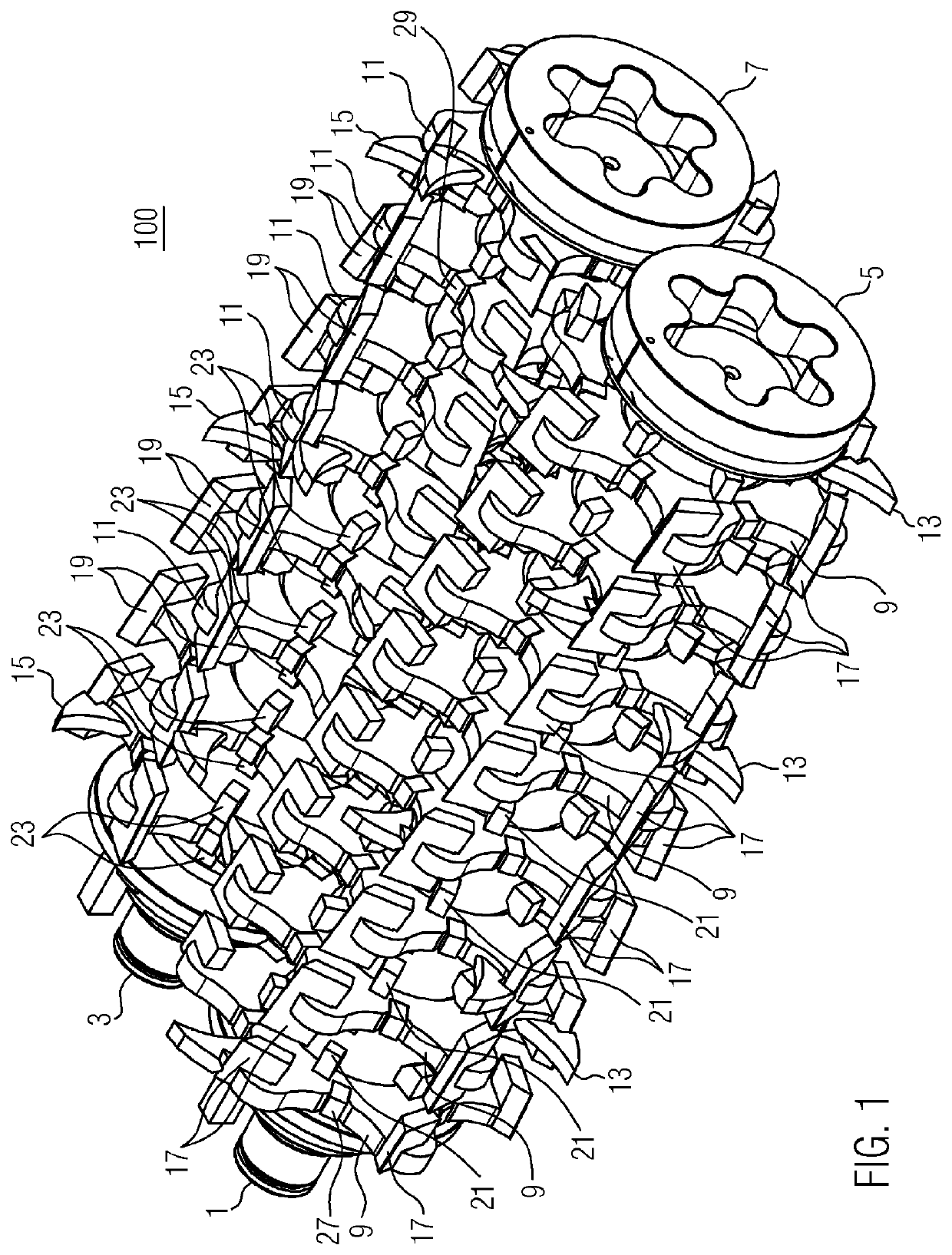
9]FIG. 1 shows a multi-region twin-shaft cutting system 100 according to the present invention. The multi-region twin-shaft cutting system 100 according to FIG. 1 shows two separate shafts 1 and 3 which are surrounded by a cylindrical roll body. It is understood that the shape of the roll body around the shaft can also have a different geometric shape, such as hexagonal or octagonal. Connection elements / couplings 5 and 7 are shown by way of example. The connection element / the coupling 5 for the left shaft 1 and the connection element / the coupling 7 for the right shaft 3 are shown in the illustrated arrangement of the cutting system 100 in FIG. 1. The two shafts 1 and 3 are arranged substantially parallel. The two shafts 1 and 3 are arranged driven in opposite manner. This means for FIG. 1 that the left shaft 1 rotates clockwise. The right shaft 3 accordingly rotates counterclockwise. The two shafts 1 and 3 can move synchronously or asynchronously. The shafts can in particular also r...


PUM


Abstract

A multi-region twin-shaft cutting system for chopping material. The cutting system includes two shafts which are arranged in parallel and are driven in an opposed manner, each shaft is surrounded by a roll body. The system additionally includes a multiplicity of supporting elements, each supporting element is fitted radially around the roll body. The system further includes a multiplicity of severing elements which are of disc- and / or plate-like design and are each fitted symmetrically or asymmetrically tangentially to the circumferential region of the supporting elements.

Description

FIELD OF THE INVENTION[0001]The present invention relates to a multi-region twin-shaft cutting system for comminuting material, in particular in the form of waste products.BACKGROUND OF THE INVENTION[0002]Commercial waste, industrial waste, domestic waste, production waste, e.g. (hard) plastics, textiles, composites, rubber, wood, or waste wood (such as pallets and chipboard), biomass, shrubbery, home and construction waste etc, prior to their final disposal or especially prior to returning them into the recovered substance cycle and for energy recovery require comminuting. Prior art knows single- or multiple-shaft choppers which are charged, for example, by wheeled loaders, forklifts, conveyors, or via a hopper for material supply.[0003]The material to be comminuted is, for example, by feeding elements conveyed into the severing region of the shafts and processed there.[0004]EP 0529221 B1 describes a twin-shaft comminuting system with breaking rollers driven in opposite manner.[000...

Claims


Application Information

Patent Timeline
Patent Type & Authority Patents(United States)
IPC IPC(8): B02C18/18B02C18/00B02C18/14B02C18/16B02C18/24B02C18/22
CPCB02C18/0084B02C18/18B02C18/182B02C18/142B02C2018/162B02C2201/06B02C18/2216B02C18/24
Inventor SEILER, STEFAN
Owner LINDNER RECYCLINGTECH
Why Eureka
Try Eureka