Deburring device

a deburring device and hand technology, applied in the direction of metal-working equipment, cleaning processes and equipment, chemistry equipment and processes, etc., can solve the problems of time-consuming, inefficient, and prone to nicks or grooves on the cut end of pipes, and achieve uniformity and efficiency.

Active Publication Date: 2020-08-13
BUNN SR KEITH R
View PDF7 Cites 0 Cited by
  • Summary
  • Abstract
  • Description
  • Claims
  • Application Information

AI Technical Summary

Benefits of technology

[0005]Accordingly, the present disclosure describes a receptacle for receiving a pipe that can deburr a pipe. More specifically, the device can clean or smooth the outside surface of a pipe from imperfections and / or deburr the inner and outer edges of the cut end of a pipe, and / or reshape the cut end of the pipe into a uniform tapered, bullnose or rounded end. The deburring device described herein is an improvement over other deburring devices because it can allow a workman to perform two or more different functions with one device, for example, to provide uniformity and efficiency in the deburring process, remove imperfections on the outside of the pipe, and / or deburr and reshape the cut end of a pipe.

Problems solved by technology

Using these tools to file or knock off burrs and then straighten the end of the pipe can be time consuming, inefficient, and potentially leave file ridges, nicks or grooves on the cut end of a pipe.
For example, using the handle or the jaws of a pair of pliers to deburr the inner and outer edges of the cut end of a pipe can leave burrs that have not been scraped off or knocked off.
In addition, this practice may leave the cut end around the outer and inner diameters of a pipe uneven by leaving file ridges, nicks or grooves caused by a filing motion, or by hitting or scraping the pipe.
These imperfections can cause a seal to fail between the pipe and a coupler, or other fitting.
Consequently, the traditional means described above are typically too abrasive to use on plastic pipes.

Method used


Image

  • Deburring device
  • Deburring device
  • Deburring device

Examples


Embodiment Construction

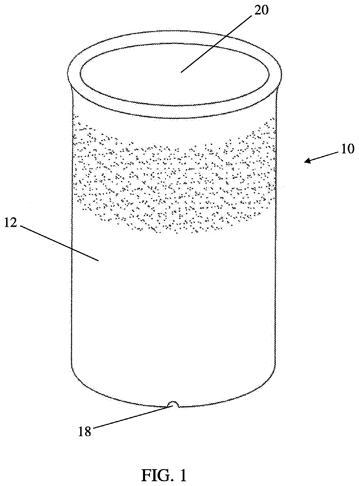
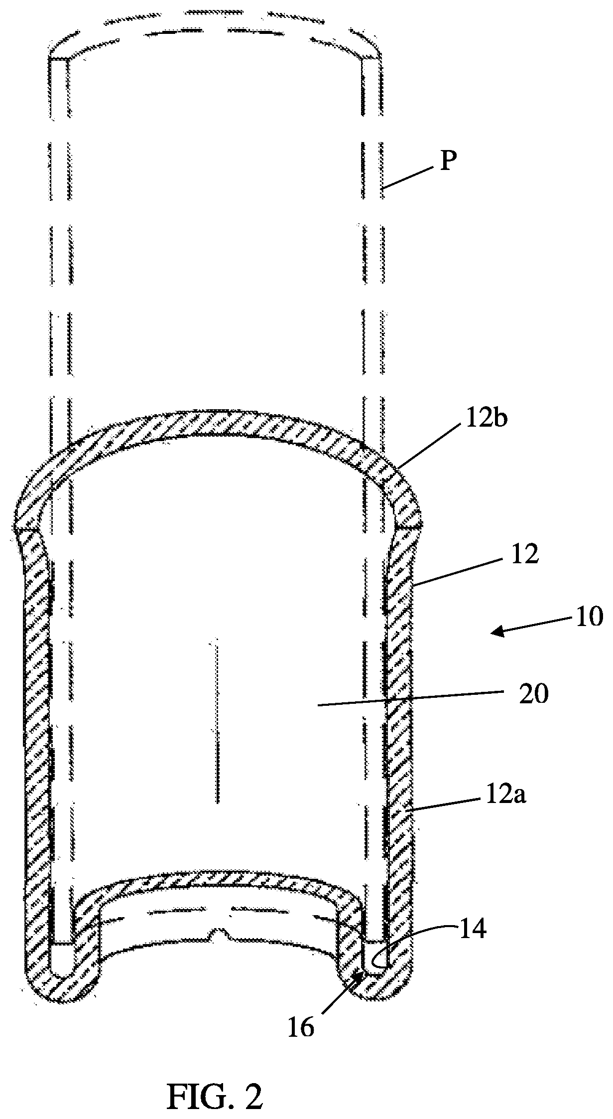
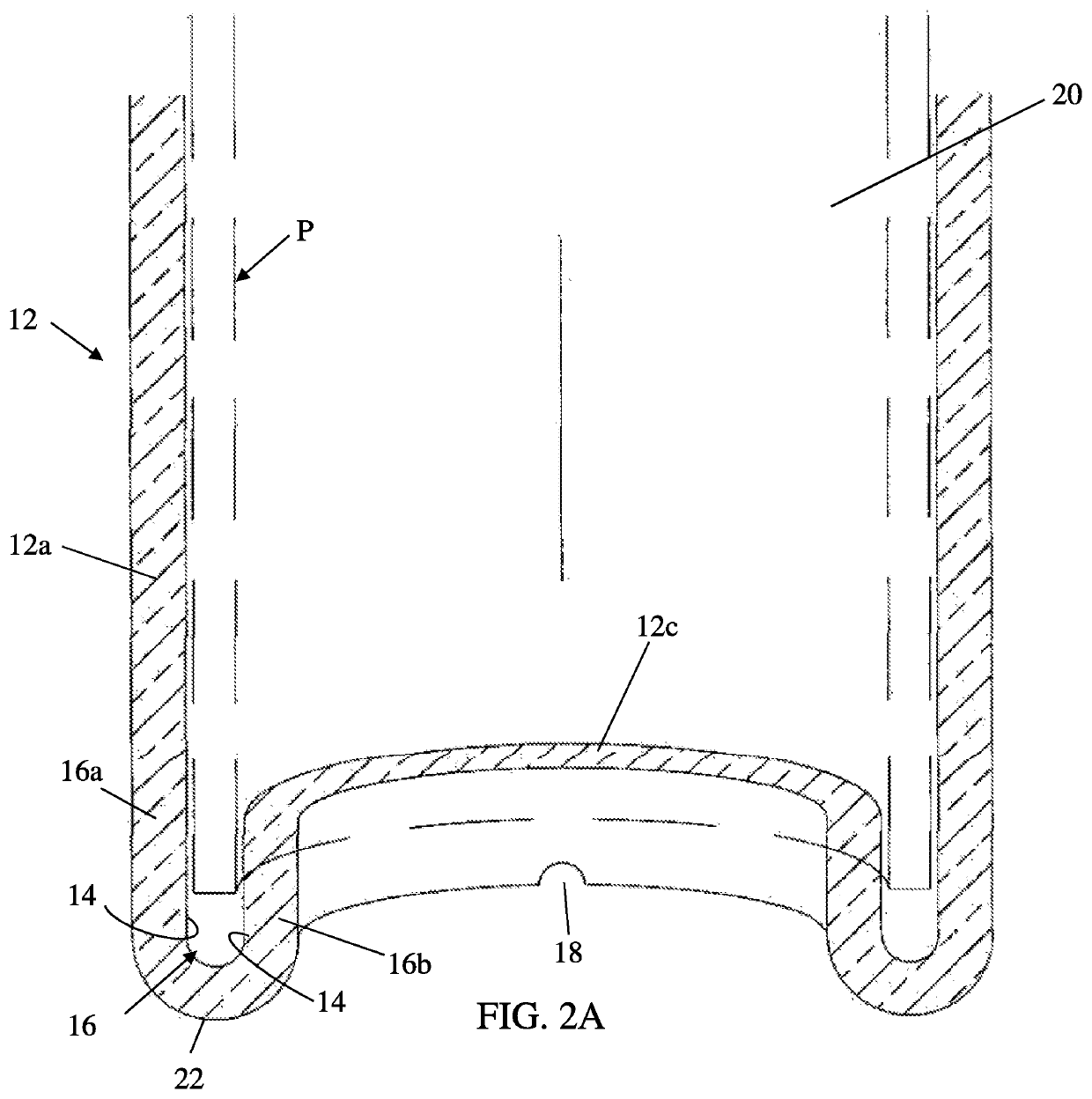
[0036]Referring to FIG. 1, the numeral 10 generally designates a deburring device. As will be more fully described below, the deburring device 10 is configured to receive a pipe for the purpose of uniformly and, optionally, simultaneously deburring the cut end to clean and / or remove imperfections on the outside of the pipe, and optionally to reshape the cut end of a pipe.

[0037]In the illustrated embodiment, deburring device 10 is constructed as a one-piece body from a material or materials, such as metal (e.g. aluminum), nickel alloy, steel (e.g. cold rolled steel), or other ferrous materials including sheet metal, tubing, solid rod, plastic, ceramic, or open web materials and may be formed by either molding, including plastic injection molding, welding, casting, or machining, including machining with a CNC machine, or any other desired manufacturing process. However, it should be understood that deburring device 10 may be formed or assembled from multiple components.

[0038]Referring...


PUM


Abstract

A deburring device includes a cylindrical body with a receptacle for receiving a pipe. The cylindrical body includes an abrasive surface provided in the receptacle, which is configured to simultaneously deburr at least two surfaces of a pipe inserted into the receptacle.

Description

[0001]The present application claims the benefit of provisional application Ser. No. 62 / 804,369 (P-102), filed Feb. 12, 2019, entitled DEBURRING DEVICE, which is incorporated by reference herein in its entirety.TECHNICAL FIELD AND BACKGROUND OF THE INVENTION[0002]The present invention generally relates to a hand deburring device.[0003]There are variety of hand tools used to deburr pipes. Common ways to deburr the cut end of a pipe are by using tools such as a file, a knife, sand paper, or a pair of pliers. Using these tools to file or knock off burrs and then straighten the end of the pipe can be time consuming, inefficient, and potentially leave file ridges, nicks or grooves on the cut end of a pipe. For example, using the handle or the jaws of a pair of pliers to deburr the inner and outer edges of the cut end of a pipe can leave burrs that have not been scraped off or knocked off. In addition, this practice may leave the cut end around the outer and inner diameters of a pipe unev...

Claims


Application Information

Patent Timeline
Patent Type & Authority Applications(United States)
IPC IPC(8): B24B9/00
CPCB24B9/007B08B9/021B08B2209/02
Inventor BUNN, SR., KEITH R.
Owner BUNN SR KEITH R
Why Eureka
Try Eureka