Method and device for producing X-ray image detector, and X-ray image detector

a technology of x-ray image detector and x-ray image, which is applied in the manufacture of electrode systems, electric discharge tubes/lamps, and screens with screens, etc. it can solve the problems of increasing the film growth time, and increasing the process time required for flattening the csi film. , to achieve the effect of efficient and uniform surface portion

Inactive Publication Date: 2006-06-27
KK TOSHIBA
View PDF8 Cites 3 Cited by
  • Summary
  • Abstract
  • Description
  • Claims
  • Application Information

AI Technical Summary

Benefits of technology

[0013]In the method and device for producing an X-ray image detector of the present invention, the X-ray light emitting phosphor film constituted of, for example, a CsI film is irradiated with the high-energy light, so that a surface portion of the X-ray light emitting phosphor film is flattened by local sublimation and / or fusion. This makes it possible to efficiently and uniformly make the surface portion of the X-ray light emitting phosphor film flat and continuous. Further, since the irradiation area of the high-energy light can be controlled according to a recessed surface shape of the input substrate or the like, which realizes applicability to various kinds of X-ray image detectors.

Problems solved by technology

In the above-mentioned method of forming the continuous film of CsI, increase in film-growth time and so on are caused and in addition, a sufficient effect of flattening the CsI film cannot be obtained.
The above-mentioned flattening method using the balls, however, requires uniform application of the weight of the balls on the entire CsI film, so that the process time required for flattening the CsI film becomes long.
Further, due to the irregular movement of the balls, it is difficult to control planarity of the CsI film.
Imparting regularity to the movement of the balls in order to control planarity will give rise to such a problem that the regular movement hinders planarity.
This method can enhance controllability over planarity of the CsI film, but on the other hand, limits the shape of the recessed surface of the input substrate due to a limited movement route of the roller used for flattening.

Method used


Image

  • Method and device for producing X-ray image detector, and X-ray image detector
  • Method and device for producing X-ray image detector, and X-ray image detector
  • Method and device for producing X-ray image detector, and X-ray image detector

Examples


Embodiment Construction

[0022]Hereinafter, embodiments of the present invention will be explained.

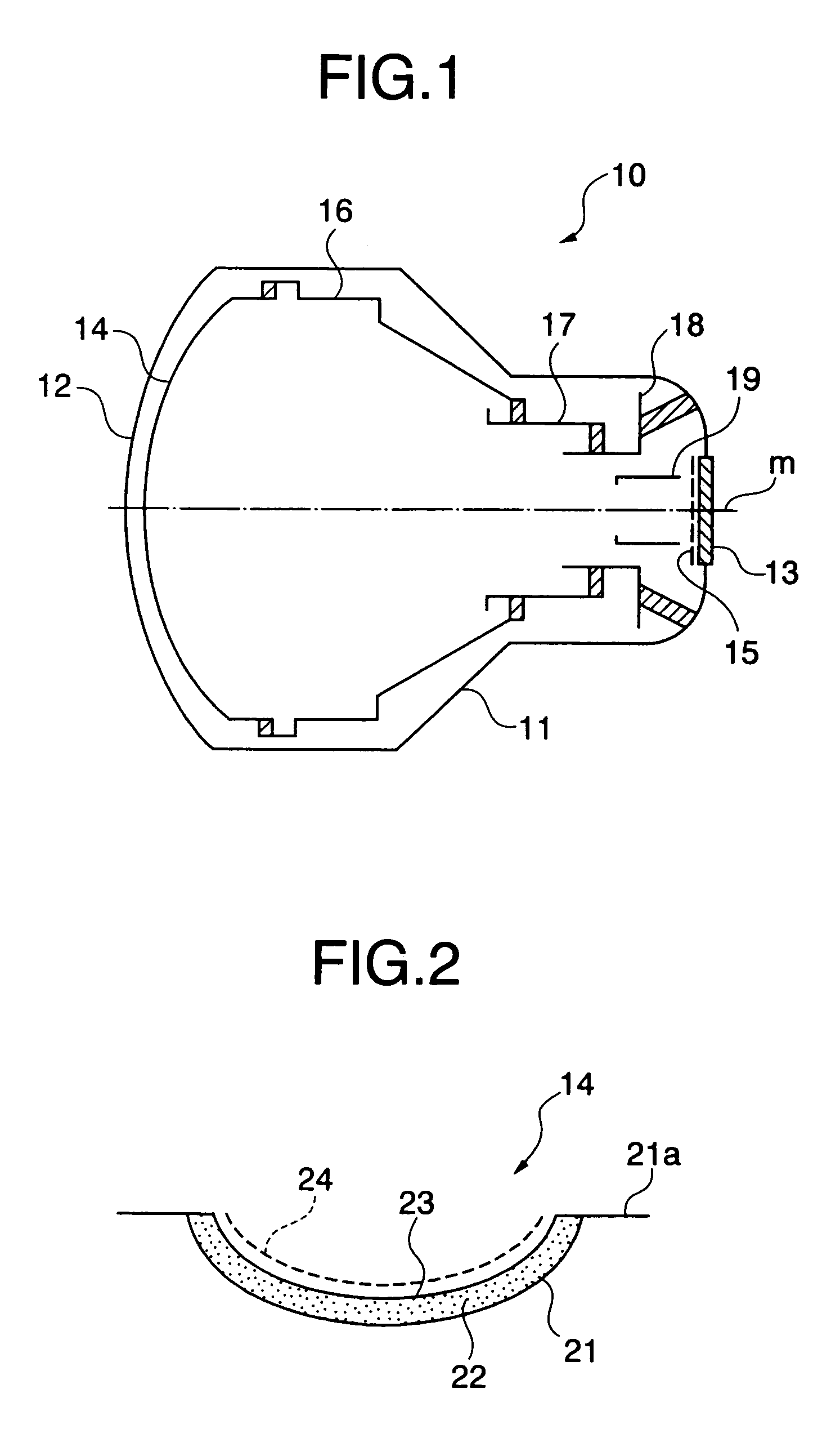
[0023]First, the configuration of an X-ray image detector to which a production method of the present invention is applied will be explained with reference to FIG. 1. FIG. 1 is a view showing the schematic configuration of a structure example of the X-ray image detector that is produced by applying the present invention. FIG. 1 shows an X-ray image tube as an example of the X-ray image detector. It should be noted that the X-ray image tube shown in FIG. 1 shows one embodiment of the X-ray image detector of the present invention.

[0024]An X-ray image tube 10 shown in the drawing has a vacuum envelope made of metal, glass, or the like. The vacuum envelope 11 constitutes an outer tube of the X-ray image tube 10 and the inside thereof is maintained vacuum at, for example, 1×10⁻⁵ Pa or less. The vacuum envelope 11 has an input window 12 provided at one end portion side thereof (a side where the X-ray is incident) an...


PUM


Abstract

An X-ray light emitting phosphor film (22) such as a CsI film that converts an X-ray to light is formed on an input substrate (21) constituting an input part of an X-ray image detector. A surface portion of the X-ray light emitting phosphor film (22) is irradiated with high-energy light having a wavelength of 500 nm or less. The surface portion of the X-ray light emitting phosphor film (22) is locally sublimated and/or fused to be flattened by the irradiation with the high-energy light. The use of the high-energy light such as a laser beam makes it possible to efficiently and uniformly flatten the surface portion of the X-ray light emitting phosphor film.

Description

TECHNICAL FIELD[0001]The present invention relates to a method and a device for producing an X-ray image detector used for a medical diagnosis apparatus, a nondestructive inspector, and the like, and to the X-ray image detector.BACKGROUND ART[0002]An X-ray image detector is an apparatus that converts an X-ray that has transmitted through a subject to visible light and is used for medical diagnosis apparatuses, nondestructive inspectors, and so on as an X-ray image intensifier or the like.[0003]Such an X-ray image detector is configured such that an input part that converts an X-ray to photoelectrons and an output part that converts the photoelectrons to visible light are respectively provided on both end portions of a vacuum envelope made of, for example, metal or glass. A focusing electrode and an anode to accelerate and focus the photoelectrons emitted from the input part and directed to the output part are interposed between the input part and the output part. An X-ray image inci...

Claims


Application Information

Patent Timeline
Patent Type & Authority Patents(United States)
IPC IPC(8): H05G1/64H01J31/50G01T1/20H01J9/233
CPCC09K11/616G21K4/00G01T1/20
Inventor YAMAGISHI, SHIROFUMI
Owner KK TOSHIBA
Why Eureka
Try Eureka