High strength lightweight composite fabric with low gas permeability

a composite fabric, low gas permeability technology, applied in the direction of weaving, synthetic resin layered products, chemistry apparatus and processes, etc., can solve the problems of reducing the tear and affecting the performance of the fabri

Inactive Publication Date: 2006-04-20
WARWICK MILLS INC
View PDF52 Cites 33 Cited by
  • Summary
  • Abstract
  • Description
  • Claims
  • Application Information

AI Technical Summary

Benefits of technology

The present invention relates to a new type of laminated material that can be used in various products like airplanes or helicopters. This material has several advantages over existing materials including better durability, improved strength, and reduced weight. In this patent, there are also provided different views and methods for understanding how the material works. Overall, this innovation provides an effective solution for creating strong yet lightweight structures with excellent performance characteristics.

Problems solved by technology

The technical problem addressed in this patent is finding better ways to make the lightest possible airplanes or aerostats without sacrificing their strength or durability. This is important due to the fact that the majority of the weight of any given airship comes from the non-lift portion - the hull. Conventional methods involve adding too much material to achieve good insulation, leading to excessive weight. A new approach is needed to address this challenge.

Method used


Image

  • High strength lightweight composite fabric with low gas permeability
  • High strength lightweight composite fabric with low gas permeability
  • High strength lightweight composite fabric with low gas permeability

Examples


Embodiment Construction

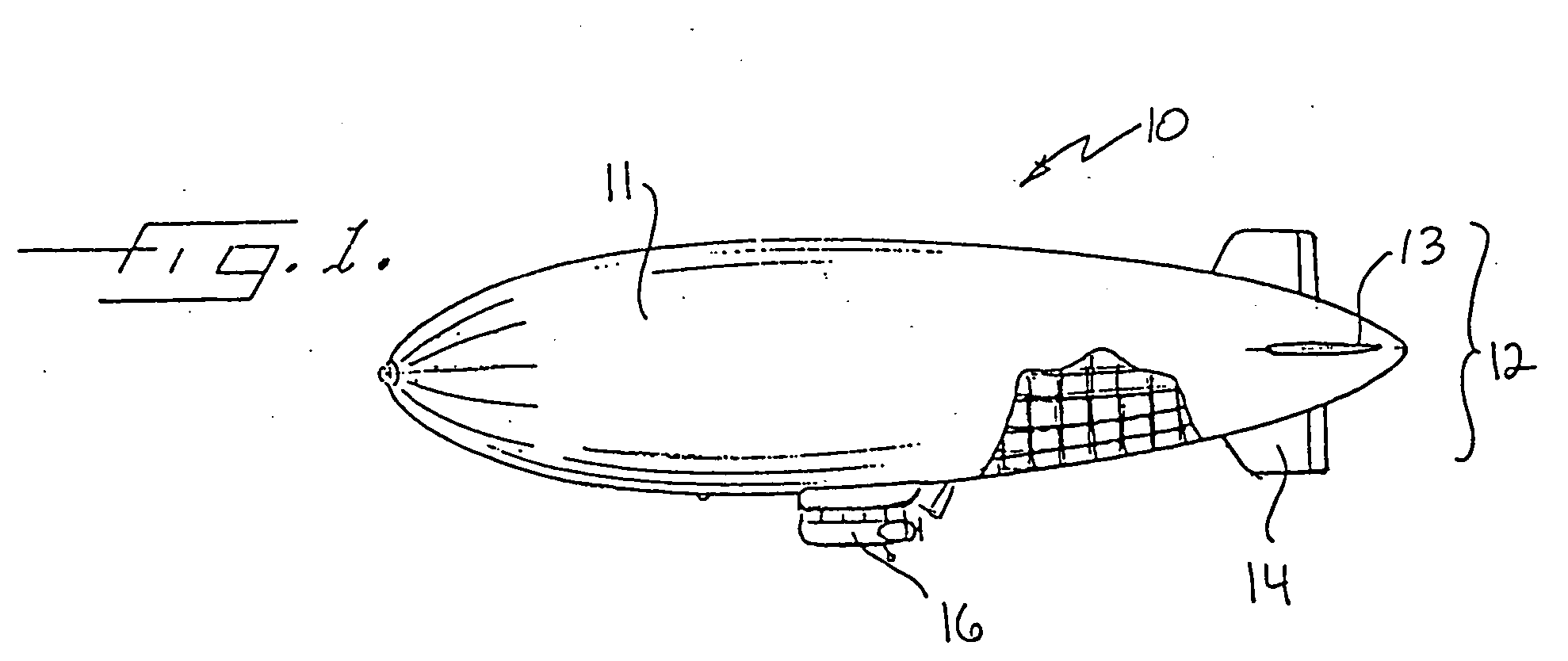
[0023]FIG. 1 is a perspective view of an airship generally designated at 10. As noted above, the airship 10 is also sometimes referred to as a “blimp,”“dirigible.” Each of these structures has the same features for the purposes of the present invention, and thus it will be understood that the invention applies to each type of airship, regardless of how it may be named in a particular application. Those of skill in this art will thus recognized that the invention is not limited to a particular classification of airship, but offers advantages regardless of the type of airship into which it may be incorporated.

[0024] As illustrated in FIG. 1, the airship 10 includes the gas envelope 11, and the tail assembly indicated by the brackets at 12. In most typical applications, the tail assembly 12 comprises both horizontal and vertical members 13 and 14 respectively. In aerostat applications in which the aerostat is tethered or otherwise maintained in a single position, the vertical and hori...


PUM

PropertyMeasurementUnit
Lengthaaaaaaaaaa
Fractionaaaaaaaaaa
Timeaaaaaaaaaa

Abstract

A flexible laminate for airship or gas enclosure applications, having a load bearing woven fabric core layer of high strength, low twist yarns, an interior side gas barrier layer, a yarn to fabric strength ratio of between about 1.36 and 1.8, a limited yarn twist, and a yarn height to width ratio of between about 1:2 and 1:7. There is an interior side gas barrier layer on one side of the load bearing layer preferably consisting of polyurethane and an exterior side layer on the other side of the load bearing layer which includes in sequence a first layer of polyurethane, a layer of film, a second layer of polyurethane, and an outermost layer of polymeric material. The laminated structure preferably has a gas transmission rate of not more than about 30 cubic centimeters in 24 hours through a one meter square area at a one atmosphere pressure differential.

Description


Claims


Application Information

Patent Timeline
Owner WARWICK MILLS INC
Why Eureka
Try Eureka