Intramedullary nail for femur fracture fixation

a technology for femur fracture and intramedullary nail, which is applied in the field of intramedullary nail for femur fracture fixation, can solve the problems of femur neck screw breaking through the femur head or of fracture becoming unstable, the height of the branches of the locking element is relatively small, and the effect of the blade is limited

Active Publication Date: 2006-04-20
SYNTHES USA
View PDF13 Cites 77 Cited by
  • Summary
  • Abstract
  • Description
  • Claims
  • Application Information

AI Technical Summary

Benefits of technology

[0013] In one embodiment, an intramedullary nail for fixation of fractures of a proximal femur includes a femur nail and a femur neck screw. The femur nail, having a longitudinal axis, includes a proximal end having a head with a borehole running diagonal to the longitudinal axis, wherein the borehole includes one or more grooves, and a distal end having a shank with a reduced diameter with respect to the head of the proximal end, wherein the shank has a cross hole and one or more axial notches. The femur neck screw includes a cluster at a proximal end, a locking element having two or more prongs arranged almost parallel to the axis of the femur neck screw, one or more longitudinal slots oriented in an axial direction, wherein at least one prong of the locking element is inserted into one of the longitudinal slots, and a threaded end at a distal end of the femur neck screw. The femur neck screw may be inserted into the borehole of the femur nail whereby axial movement of the femur neck screw in the borehole of the femur nails is achieved making possible a twisting lock, and the twisting lock is formed by a positive connection between the locking element and the femur nail, and between the locking element and the femur neck screw.

Problems solved by technology

If the femur neck screw does not stop this shortening, there may be a danger of the femur neck screw breaking through the femur head or of the fracture becoming unstable.
However, the height of the branches of the locking element is relatively small, since they are governed by the femur nail only in the femur neck screw slots, and thus their effect as blades is limited.
However, such an operation is more costly and there exists a problem that with small jaw necks the two screws will hardly find any place or none at all to be secured to.
It is, however, unfortunate that the spiral blade does not support the femur head sufficiently in the axial direction.
A particular problem of the femur neck screw US2002 / 0045900 is that there is reduced sliding ability of the screw / locking element along the screw axis during the drilling in of the femur nails, since upon sinking the branches of the u-shaped locking element are spread by the nail against slots of smaller depth in the screw, and they may block themselves during the drilling in of the femur nail.

Method used


Image

  • Intramedullary nail for femur fracture fixation
  • Intramedullary nail for femur fracture fixation
  • Intramedullary nail for femur fracture fixation

Examples


Embodiment Construction

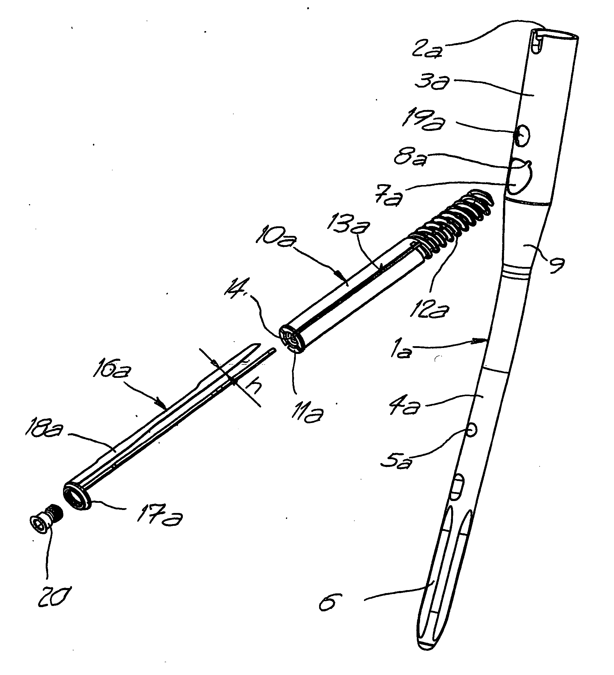
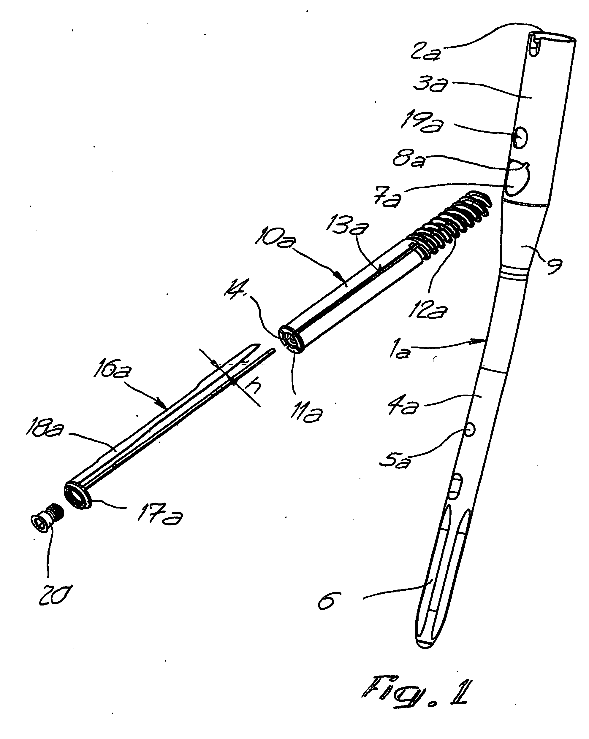
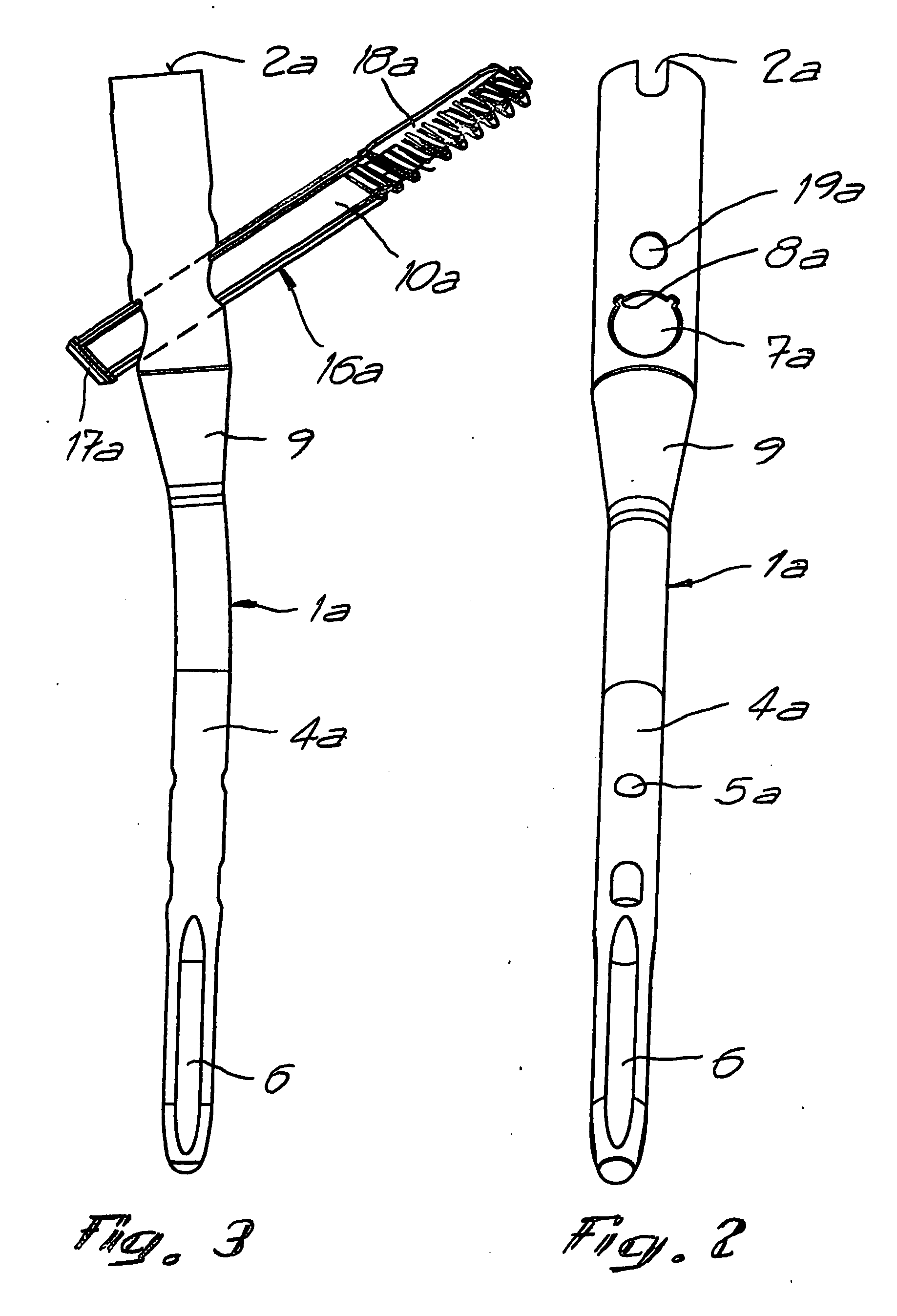
[0025] The intramedullary nail shown in FIGS. 1 to 4 essentially consists of a femur nail 1a and a femur neck screw 10a. The femur nail 1a at its proximal end 2a includes a head 3a. At the distal end, opposite the head 3a, the femur nail 1a includes a shank 4a with a reduced diameter as compared to the proximal end 2a. The transient area between head 3a and shank 4a is designed as cone 9. At the front, the shank 4a is provided with at least one cross hole 5a, which serves as an axial safety device of the femur nail 1a in the bone. In addition, shank 4a includes axial notches 6. The head 3a is provided with at least one borehole 7a, running diagonally to the longitudinal axis, and one auxiliary drilling hole 19a, running parallel to it. The borehole 7a includes at least one groove 8a. An auxiliary wire (not shown) is introduced by the auxiliary drilling 19a when pivoting the femur neck screw 10a, in order to prevent a secure driving of the bone fragment.

[0026] The femur neck screw 1...


PUM


Abstract

The invention concerns an intramedullary nail for the fixation of fractures of the proximal femur, with a femur neck screw (10a), installable with a proximal femur nail (1a), into the intramedullary area, by a diagonal bore (7a), running to the longitudinal axis of the femur nail (1a), from the side of the femur nail (1a), and a locking element (16a) with at least one prong (18a) parallel to the axis of the femur neck screw (10a). A positive connection between the locking element (16a) and a groove (8a) in the bore (7a) of the femur nail (1a) forms a twisting lock of the femur neck screw (10a) and, allows for the axial movement of the femur neck screw (10a) in the bore (7a) of the femur nail (1a).

Description

CROSS REFERENCE TO RELATED APPLICATION [0001] This application is a continuation of International Patent Application No. PCT / IB2004 / 001064, filed Apr. 7, 2004, the entire contents of which is expressly incorporated herein by reference. The International Patent Application No. PCT / IB2004 / 001064 claims priority from Swiss Application No. 2003 0648 / 03, filed Apr. 9, 2003.TECHNICAL FIELD [0002] The present invention relates generally to an intramedullary nail for femur fracture fixation. BACKGROUND OF THE INVENTION [0003] It is known in the art to use screws and blades as fastening parts, and in particular the so-called spiral blades. Screws provide an excellent grip in the axial direction, a moderate grip in the radial direction (perpendicular to the screw axis), and almost no grip against rotation around the screw axis. Opposing blades provide a very good grip in radial direction as well as against rotation around the blade axis, but almost no grip in the axial direction. [0004] It is...

Claims


Application Information

Patent Timeline
Patent Type & Authority Applications(United States)
IPC IPC(8): A61B17/56A61B17/74A61B17/78A61B17/86
CPCA61B17/744A61B2017/8655
Inventor ASCHMANN, FELIX
Owner SYNTHES USA
Why Eureka
Try Eureka