Impact of copper and carbon on mechanical properties of iron-carbon-copper alloys for powder metal forging applications

a technology of iron-carbon-copper alloys and mechanical properties, applied in the direction of mechanical equipment, shafts and bearings, connecting rods, etc., can solve the problems of contradictory and incomplete findings of these reports, and the use of higher copper content in wrought materials

Inactive Publication Date: 2006-04-27
METALDYNE LLC
View PDF5 Cites 39 Cited by
  • Summary
  • Abstract
  • Description
  • Claims
  • Application Information

AI Technical Summary

Benefits of technology

The patent describes how adding different amounts of copper and forged carbon can affect the strength of certain materials. This helps explain why some materials are stronger than others.

Problems solved by technology

The technical problem addressed in this patent text is how to improve the fatigue strength of connecting roods made through sinter-forging technology while maintaining their overall efficiency and reducing costs. Specifically, the influence of copper and carbon content on the strength of iron-copper-carbon systems needs to be further understood.

Method used


Image

  • Impact of copper and carbon on mechanical properties of iron-carbon-copper alloys for powder metal forging applications
  • Impact of copper and carbon on mechanical properties of iron-carbon-copper alloys for powder metal forging applications
  • Impact of copper and carbon on mechanical properties of iron-carbon-copper alloys for powder metal forging applications

Examples


Embodiment Construction

[0028] While the present invention is described with reference to the preferred embodiment, it should be clear that the present invention should not be limited to this embodiment. Therefore, the description of the preferred embodiment herein is illustrative of the present invention and should not limit the scope of the invention as claimed.

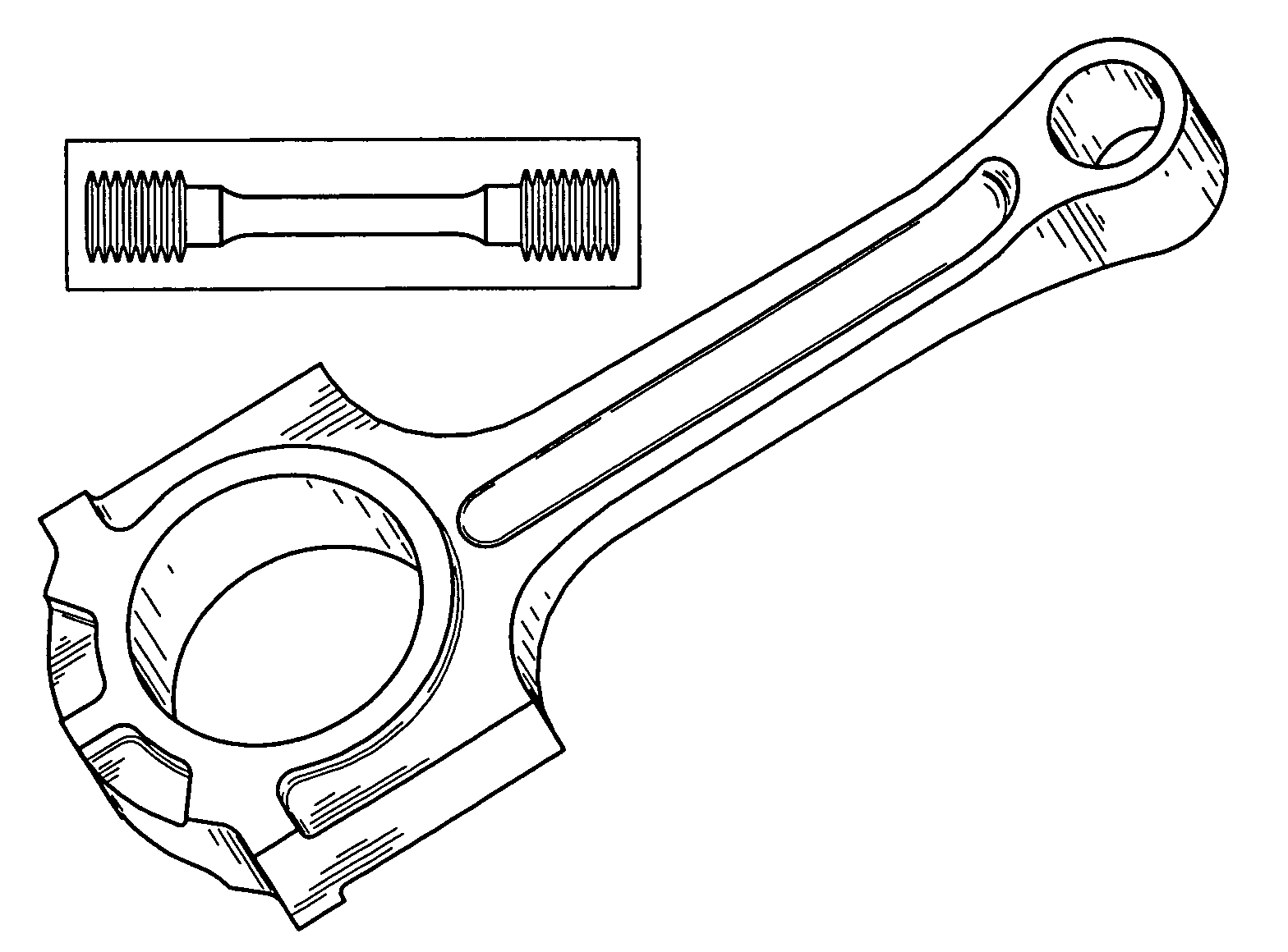
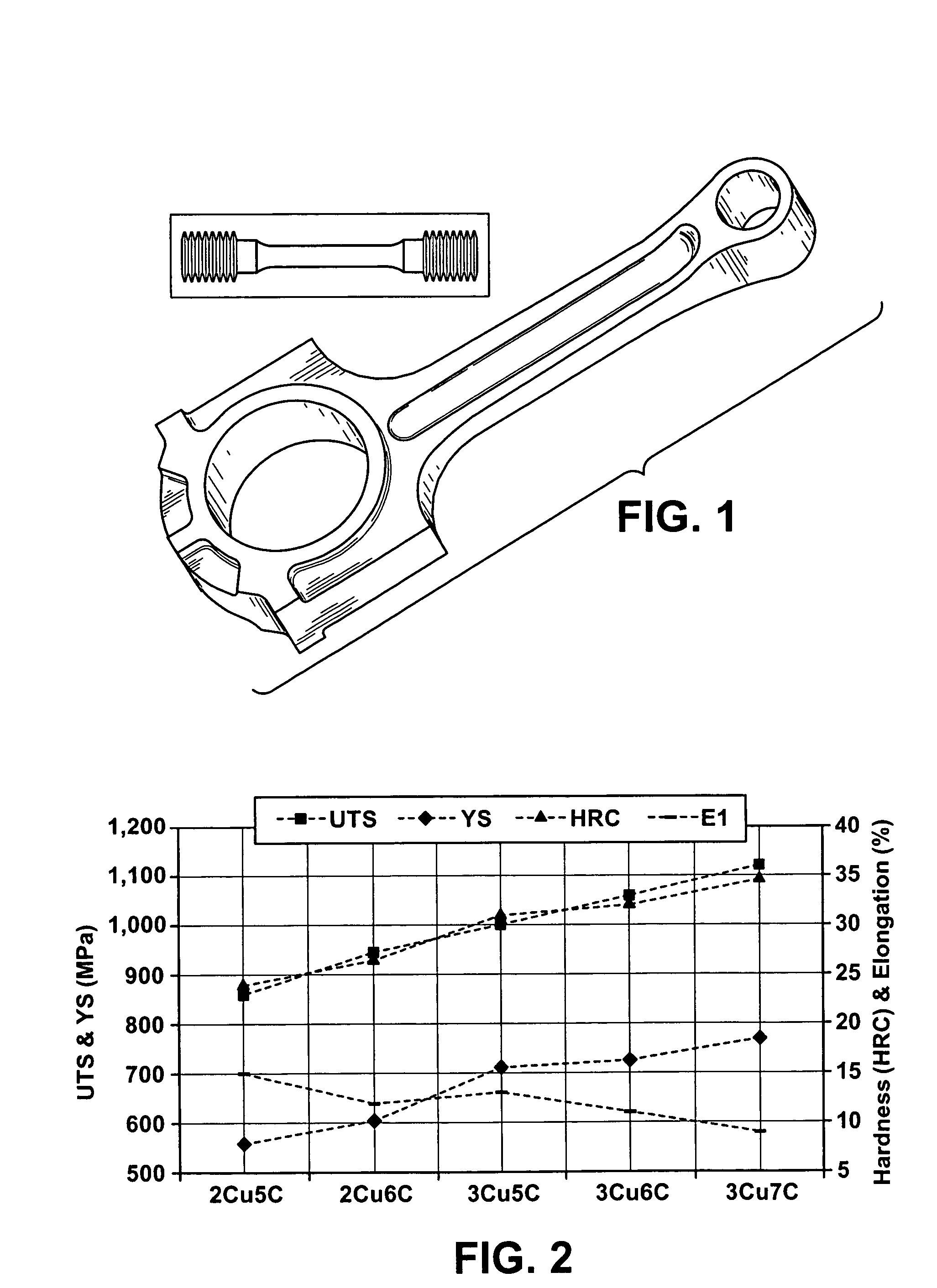
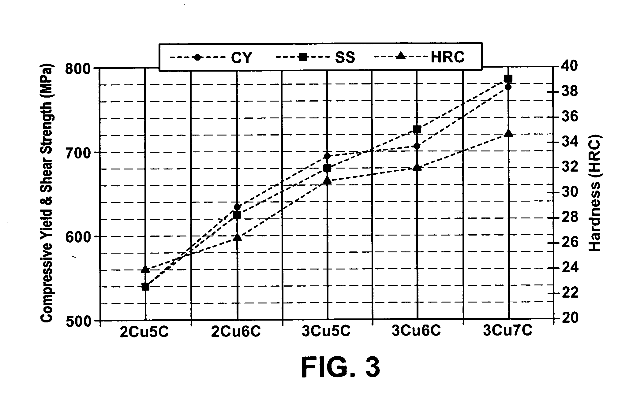
[0029] The effect of copper contents (from 2% to 4%) on iron-based powder metal sintered-forged materials was studied. This study also included the previously developed HS150™ in its results. The conclusion was that mechanical properties peak at the level of approximately 3% copper under processing conditions considered. Graphite contents of approximately 0.58%, 0.68%, and 0.78% were admixed, along with approximately 2.0% and 3.0% copper, and approximately 0.32% manganese sulfide (MnS), into an atomized ferrous base powder. Static and dynamic tests were carried out on specimens machined out of fully dense (hot forged) components and pucks. Correl...


PUM

PropertyMeasurementUnit
Fractionaaaaaaaaaa
Fractionaaaaaaaaaa
Fractionaaaaaaaaaa

Abstract

There was perceived a lack of information regarding higher strength materials for sinter-forging automotive applications. Work, therefore, was undertaken to develop new higher strength materials for sinter-forging automotive applications and to fill this lack of information. Accordingly, a connecting rod that comprises an iron-based powder metal mixture was developed. The mixture comprises between 3.01% and 3.03% by weight of copper, between 0.57% and 0.64% by weight of carbon, between 0.32% and 0.33% by weight of manganese, and about 0.13% by weight of sulfur.

Description


Claims


Application Information

Patent Timeline
Owner METALDYNE LLC
Why Eureka
Try Eureka