Photoelectric conversion device and method for producing same

a technology of photoelectric conversion device and photoelectric conversion method, which is applied in the direction of electrochemical generator, sustainable manufacturing/processing, final product manufacture, etc., can solve the problem that the photoelectric conversion efficiency of the dye-sensitive photoelectric conversion device is not necessarily high enough

Inactive Publication Date: 2002-04-11
FUJIFILM CORP
View PDF0 Cites 176 Cited by
  • Summary
  • Abstract
  • Description
  • Claims
  • Application Information

AI Technical Summary

Benefits of technology

0169] As for the structure illustrated in FIG. 3, on the transparent substrate 50a partially having the metal lead 11 is disposed the transparent electrically conductive layer 10a, the undercoating layer 60, the photosensitive layer 20, the charge transfer layer 30 and the counter electrically conductive layer 40 are laminated in this order, and the substrate 50 is further placed thereon. This structure allows light incidence from the electrically conductive layer side.
0170] As for the structure illustrated in FIG. 4, the photosensitive layer 20 is disposed on the substrate 50 having the electrically conductive layer 10 through the undercoating layer 60, the charge transfer layer 30 and the transparent counter electrically conductive layer 40a are

Problems solved by technology

However, the conventional, dye-sensitized photoelectric conversion devices d

Method used


Image

  • Photoelectric conversion device and method for producing same
  • Photoelectric conversion device and method for producing same
  • Photoelectric conversion device and method for producing same

Examples


example 1

[0182] 1. Preparation of Coating Dispersion Containing Titanium Dioxide

[0183] A titanium dioxide dispersion was prepared in the same manner as a method disclosed in C. J. Barbe, et al, J. Am. Ceramic Soc., 80, 3157 except that the autoclave temperature was 230.degree. C. The weight ratio of titanium dioxide fine particles was 11 weight % and the average diameter thereof was approximately 10 nm in the titanium dioxide dispersion. Then, polyethylene glycol (average molecular weight: 20000, Wako Pure Chemical Industries, Ltd.) was added to the titanium dioxide dispersion and mixed to prepare a coating dispersion containing titanium dioxide, weight ratio of the polyethylene glycol being 20 weight % to 100 weight % of the titanium dioxide fine particles.

[0184] 2. Preparation of Dye-Adsorbed Titanium Dioxide Electrode

[0185] (1) Comparative Electrode

[0186] The above coating dispersion was applied onto an electrically conductive surface of a transparent conductive support into a thickness o...

example 2

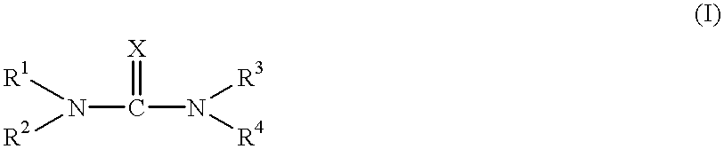
[0212] Photoelectric conversion devices were produced in the same manner as Example 1 except that a merocyanine dye or a squalilium dye was used instead of the ruthenium complex dye. Incidentally, concentration of the dye in the dye adsorption solution was 1.times.10.sup.-4 mol / l. Each of the resultant photoelectric conversion devices was measured with respect to the photoelectric conversion efficiency in the same manner as Example 1. As a result, the photoelectric conversion devices of the present invention, in which the semiconductor fine particle was treated with the compound (I), exhibited more excellent photoelectric conversion efficiency than those of the comparative photoelectric conversion devices.

example 3

[0213] 1. Preparation of Coating Dispersion Containing Titanium Dioxide

[0214] A coating dispersion containing titanium dioxide was prepared in the same manner as Example 1.

[0215] 2. Preparation of Dye-Adsorbed Titanium Dioxide Electrode

[0216] (1) Comparative Electrode

[0217] Comparative Electrode T-1 was prepared in the same manner as Example 1 using the above coating dispersion.

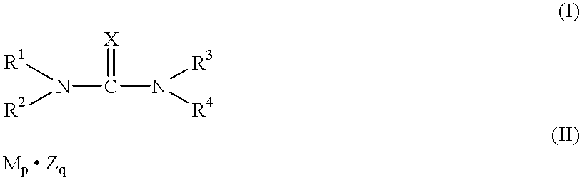
[0218] Further, Comparative Electrode T-1' was prepared in the same manner as the Comparative Electrode T-1 except that to the dye adsorption solution was added the compound (II-1), lithium iodide. Concentration of the compound (II-1) in the dye adsorption solution was 0.01 mol / l.

[0219] (2) Treatment Electrode

[0220] Electrodes T-3 to T-11 were prepared in the same manner as the Comparative Electrode T-1 except that the semiconductor fine particle was treated with the compound (I) and the compound (II) shown in Table 6, respectively.

7 TABLE 6 Compound (I) and Compound (II) Electrode Pre-Treatment Simultaneous ...


PUM


Abstract

A method for producing a photoelectric conversion device comprising a conductive support and a photosensitive layer containing a semiconductor fine particle on which a dye is adsorbed, wherein the semiconductor fine particle is treated with a compound represented by the following general formula (I): wherein X represents an oxygen atom, a sulfur atom, a selenium atom or NY, in which Y represents a hydrogen atom, an aliphatic hydrocarbon group, a hydroxyl group or an alkoxy group; R1, R2, R3 and R4 independently represent a hydrogen atom, an aliphatic hydrocarbon group, an aryl group, a heterocyclic group, -N(R5)(R6), -C(=O)R7, -C(=S)R8, -SO2R9 or -OR10; R5 and R6 few independently have the same meaning as the R1, R2, R3 and R4; R7, R8 and R9 independently represent a hydrogen atom, an aliphatic hydrocarbon group, an aryl group, a heterocyclic group, -N(R5)(R6), -OR10 or -SR11; and R10 and R11 independently represent a hydrogen atom or an aliphatic hydrocarbon group.

Description

[0001] The present invention relates to a method for producing a photoelectric conversion device comprising a semiconductor fine particle sensitized by a dye, a photoelectric conversion device produced by the method and a photoelectric cell comprising the photoelectric conversion device.[0002] Photoelectric conversion devices have been used for optical sensors, copying machines, photovoltaics, etc. Such photoelectric conversion devices that use a metal, a semiconductor, an organic pigment, a dye, a combination thereof, etc. have been made practicable.[0003] Photoelectric conversion devices using a semiconductor fine particle sensitized by a dye, hereinafter referred to as "dye-sensitized photoelectric conversion device," and materials and producing methods therefor have been disclosed in U.S. Pat. Nos. 4,927,721, 4,684,537, 5,084,365, 5,350,644, 5,463,057, 5,525,440, WO 98 / 50393, Japanese Patent Laid-Open No. 7-249790 and Japanese Patent Publication No.10-504521. The dye-sensitized ...

Claims


Application Information

Patent Timeline
IPC IPC(8): H01G9/20H01L51/00H01L51/30
CPCH01G9/2009H01G9/2027H01G9/2031Y02E10/542H01L51/0077H01L51/0078H01L51/0084H01L51/005Y02P70/50H10K85/60H10K85/311H10K85/30H10K85/341
Inventor YOSHIKAWA, MASARU
Owner FUJIFILM CORP
Why Eureka
Try Eureka