Electromagnetic pilot type directional control valve

a directional control valve, electric motor technology, applied in the direction of valve operating means/releasing devices, mechanical equipment, transportation and packaging, etc., can solve the problem of light difficulty in workability, achieve superior workability, facilitate design, and facilitate disassembly and reassembly.

Inactive Publication Date: 2006-04-27
SMC CORP
View PDF9 Cites 4 Cited by
  • Summary
  • Abstract
  • Description
  • Claims
  • Application Information

AI Technical Summary

Benefits of technology

[0006] It is an object of the invention to provide an electromagnetic pilot type directional control valve superior in workability and maintenanceability in which parts such as a pilot valve and a printed circuit board related thereto can be mounted efficiently to a top surface of a housing and operations such as disassembly or reassembly of the respective parts can be achieved in sequence easily without forming pilot flow channels which are interlacing and being bent in a complicated manner or a plurality of screw holes for mounting the pilot valve on the housing.
[0013] According to the present invention, since the pilot valve is mounted to the valve adapter, and the pilot supply flow channel and the pilot communication hole are formed utilizing the valve adapter, it is not necessary to form the pilot flow channels extending in the interlacing directions and being bent in a complicated manner on the housing or to select positions for forming screw holes for mounting the pilot valve in order to avoid interference with these flow channels, whereby easiness of designing and superior workability are achieved. Also, the parts such as the pilot valve and the printed circuit board can be assembled on the top surface of the housing efficiently by utilizing the valve adapter, and hence easy disassembly and reassembly and superior maintenanceability are achieved.

Problems solved by technology

Therefore, there is a slight difficulty in workability.

Method used


Image

  • Electromagnetic pilot type directional control valve
  • Electromagnetic pilot type directional control valve
  • Electromagnetic pilot type directional control valve

Examples


Embodiment Construction

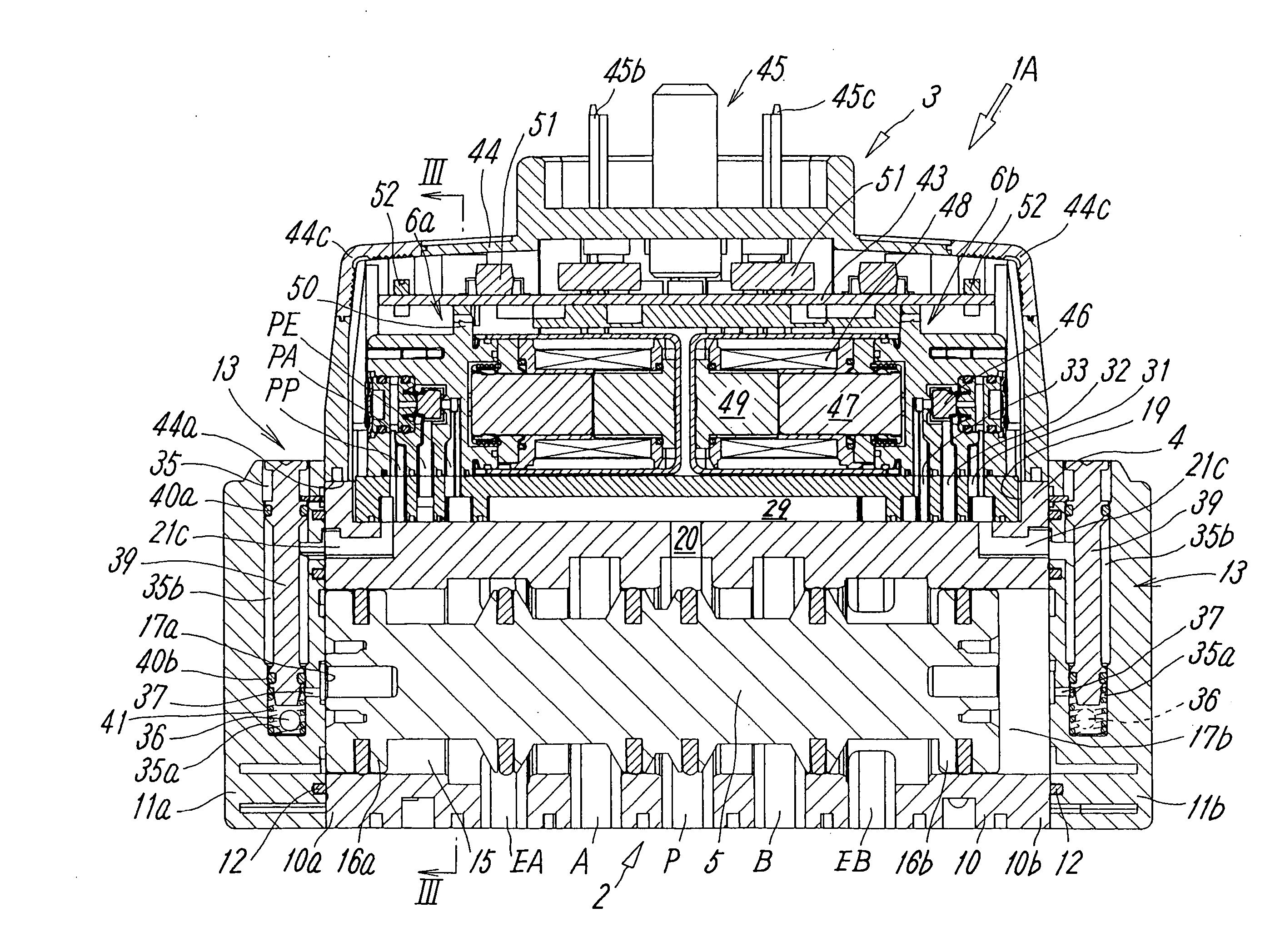
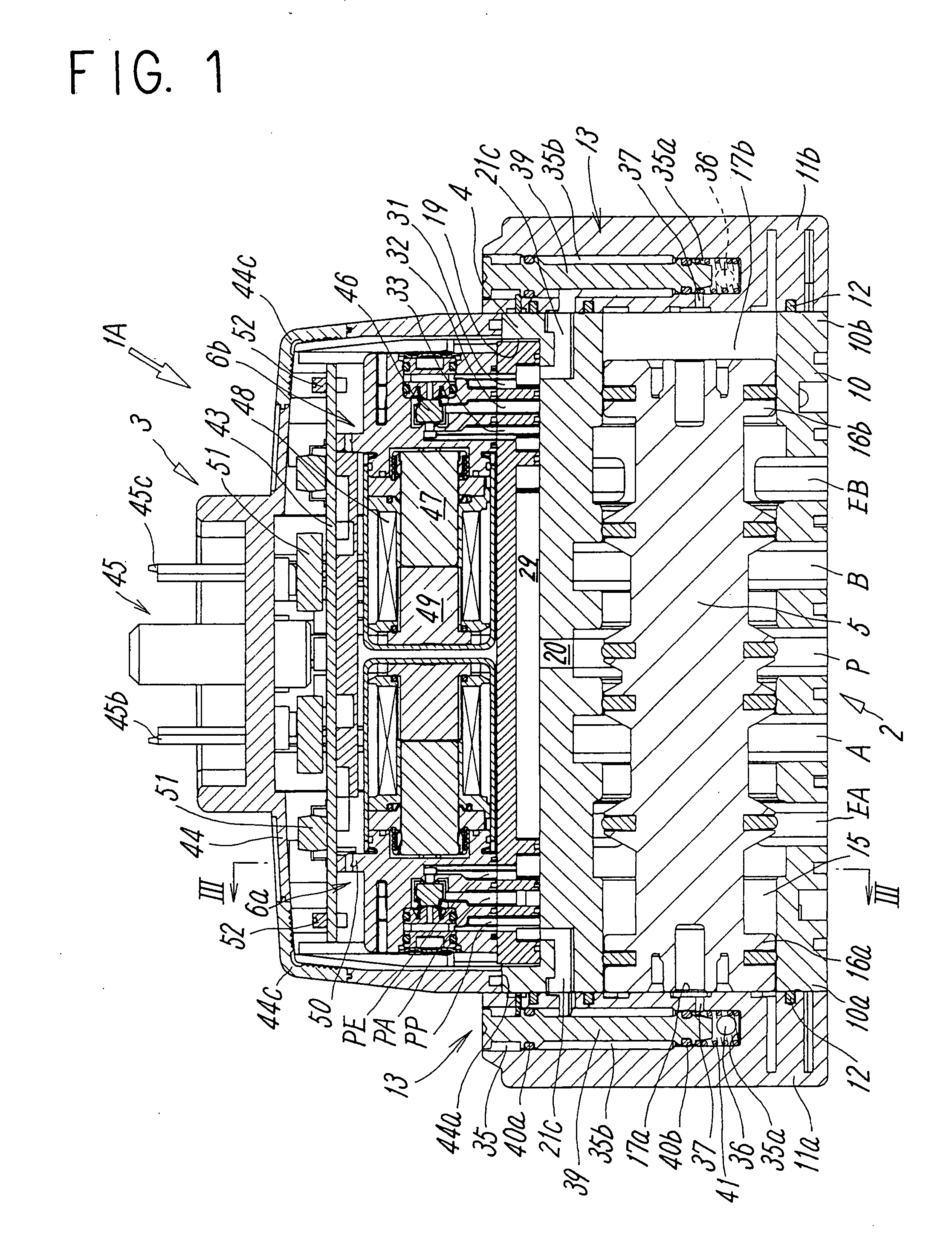
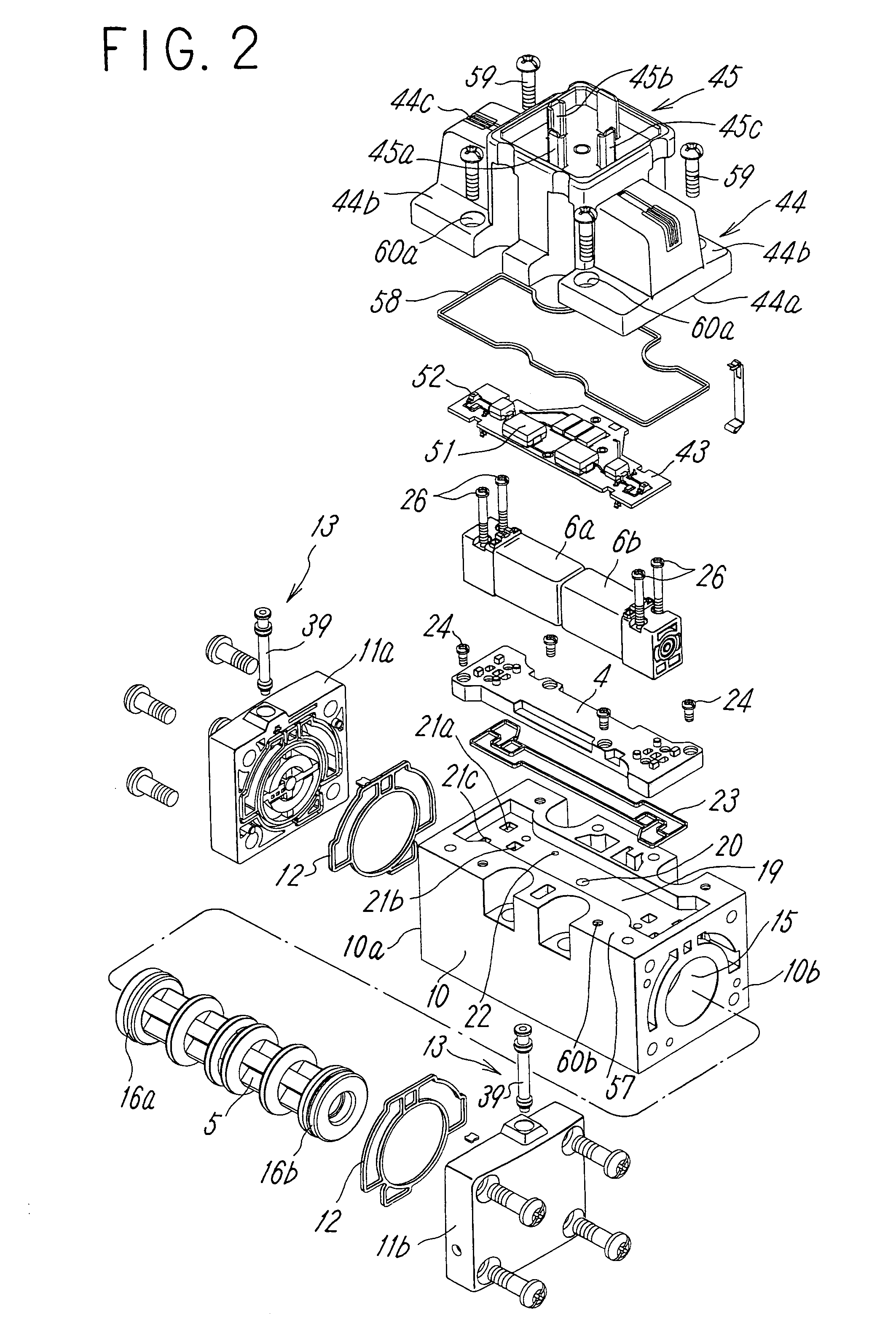
[0024]FIG. 1 and FIG. 2 show a first embodiment of an electromagnetic pilot type directional control valve according to the present invention. The directional control valve 1A is a double-pilot type directional control valve and includes a main valve section 2 for diverting a flow channel of a main fluid by a spool 5 and a pilot operating unit 3 for driving the spool 5 by controlling the pilot fluid by two electromagnetically operated pilot valves 6a, 6b. The pilot operating unit 3 is installed on a top surface of the main valve unit 2 via a valve adapter 4.

[0025] The main fluid and the pilot fluid may either be liquid or air.

[0026] The main valve section 2 has a 5-port valve structure and includes a housing 10 being elongated in an axial direction and having substantially rectangular shape in cross section, and a first end plate 11a and a second end plate 11b mounted airtightly to a first end 10a and a second end 10b of the housing in the axial direction via gaskets 12. The end p...


PUM


Abstract

To obtain a directional control valve superior in workability and maintenanceability by mounting a pilot valve, a printed circuit board and the like on a top surface of a main valve section efficiently so that easy disassembly and assembly are achieved. A valve adapter is mounted on a top surface of a housing of a main valve section with first screws, pilot valves are mounted on the valve adapter with second screws, a printed circuit board is disposed above the pilot valves, and is electrically connected thereto, a protective cover for covering the valve adapter, the pilot valves, and the printed circuit board is mounted airtightly to the top surface of the housing with third screws, a pilot supply flow channel is formed between the valve adapter and the housing, and relay holes for bringing the pilot valves into communication with pilot flow channel ports are provided on the valve adapter.

Description

TECHNICAL FIELD [0001] The present invention relates to an electromagnetic pilot type directional control valve configured to drive a spool by an electromagnetically operated pilot valve. BACKGROUND ART [0002] An electromagnetic pilot type directional control valve configured to drive a spool that slides within a valve aperture for switching flow channel by one or two electromagnetically operated pilot valves is known in the related art. In the directional control valves of this type, the pilot valve is mounted to one or both ends of the housing in the axial direction or on a top surface of the housing. The directional control valve having a pilot valve on the top surface of the housing as in the latter case has an advantage such that the widthwise length can be reduced, and hence is suitable to be used in a space which is narrow in width. [0003] Patent Document 1 discloses a directional control valve having a pilot valve mounted on a top surface of housing. This directional control...

Claims


Application Information

Patent Timeline
Patent Type & Authority Applications(United States)
IPC IPC(8): F15B13/043
CPCF15B13/0433F15B13/0853F15B13/0857F15B13/0864Y10T137/86614Y10T137/8671F16K11/07F16K31/0603
Inventor MATSUMOTO, TAKUMIHAYASHI, BUNYA
Owner SMC CORP
Why Eureka
Try Eureka