Method and apparatus for coating of substrates

a substrate and coating technology, applied in the field of methods and apparatuses for coating devices, can solve the problems of affecting the functioning of the device, affecting the function and geometry of the medical device, and affecting the device's function,

Inactive Publication Date: 2006-04-27
SURMODICS INC
View PDF95 Cites 70 Cited by
  • Summary
  • Abstract
  • Description
  • Claims
  • Application Information

AI Technical Summary

Benefits of technology

[0010] In an embodiment, the invention includes a method for coating small diameter medical devices including the steps of removing a static charge from a small diameter medical device, placing the small diameter medical device on a device rotator, the device rotator comprising a pair of r

Problems solved by technology

Medical devices are becoming increasingly complex in function and geometry.
Traditional coating methods, such as dip coating, are often undesirable for coating these complex geometries since coating solution may get entrapped in the device structure.
This entrapped solution may cause webbing or bridging of the coating solution and may hinder the device from functi

Method used


Image

  • Method and apparatus for coating of substrates
  • Method and apparatus for coating of substrates
  • Method and apparatus for coating of substrates

Examples


example 1

Coating Apparatus

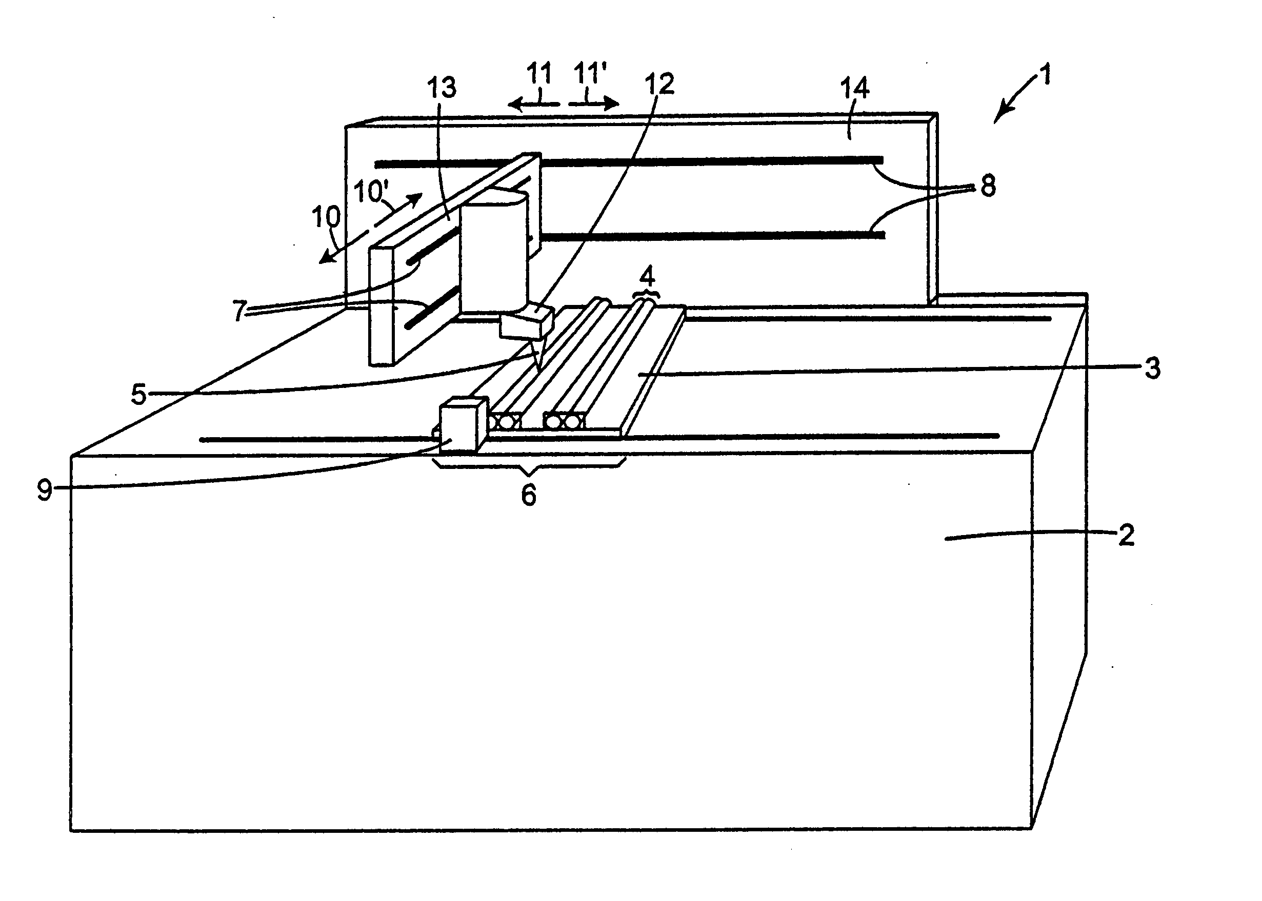
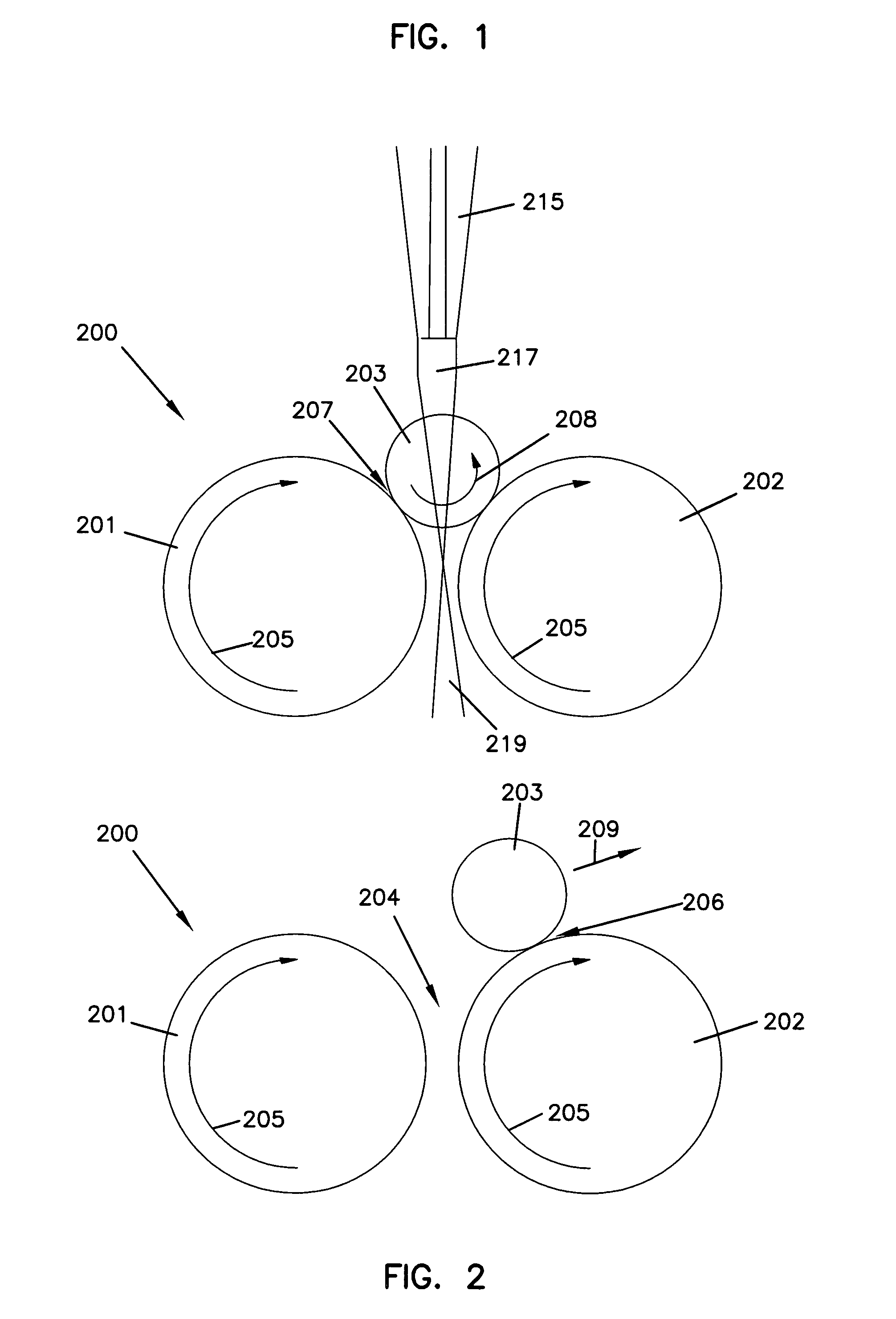
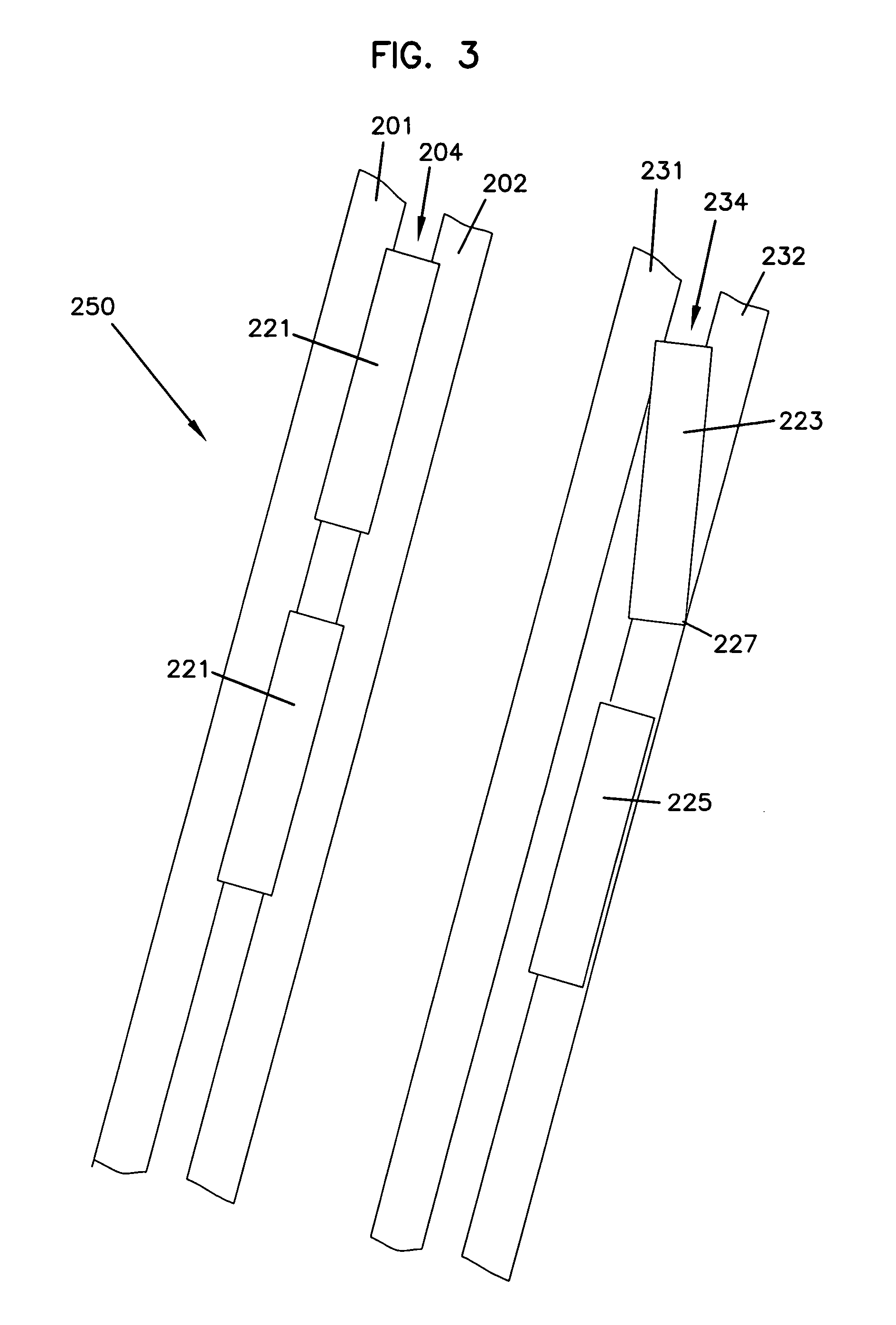
[0195] An automated coating apparatus having an ultrasonic spray nozzle (SonoTek; Milton, N.Y.) attached to a robotic arm was used to coat stainless steel stents. A coating solution was supplied to the spray nozzle using syringe pump (kdScientific Inc., New Hope, Pa.). Stents were placed in the groove on pairs of rollers, above the gap between the each roller of the pair. A total of six pairs of rollers were attached to a tray and brought into a coating zone. The spray nozzle travels over the each roller, dispensing coating solution in a narrow band on the stents. When the spray nozzle reaches the end of Roller #6, Rollers #1-3 index and rotate the stents. When the spray nozzle reaches the end of Roller #3, Rollers #4-6 index. The capacity of the coating apparatus is about 50 stents, each stent 18 mm in length.

example 2

Application of a Base Coat Material

[0196] The coating apparatus as described in Example 1 was used to provide a base coat to stents having a size of 18 mm in length by 1.5 mm in diameter. Based on the surface area of the stents, a basecoat weight range was chosen to be in the range of 600-660 μg per stent. Prior to the coating procedure, stents were individually weighed. Stents were placed on the pairs of rollers and a base coat material was deposited on the stents.

[0197] A coating solution was prepared containing pBMA (poly(butylmethacrylate)) at a concentration of 1.67 g / l, pEVA (poly(ethylene-co-vinyl acetate)) at a concentration of 1.67 g / l, and an immunosuppressive antibiotic at a concentration of 1.67 g / l, dissolved in tetrahydrofuran. The solution delivery rate from the nozzle was 0.15 ml / min; the nozzle air pressure was maintained at 2.5 psi; and the sonicator power was set at 0.6 watts. The distance from the nozzle tip to the surface of the stent was adjusted to be in the...


PUM


Abstract

The invention relates to methods and apparatuses that reduce problems encountered during coating of a device, such as a medical device having a cylindrical shape. In an embodiment, the invention includes an apparatus including a bi-directional rotation member. In an embodiment, the invention includes a method with a bi-directional indexing movement. In an embodiment, the invention includes a coating solution supply member having a major axis oriented parallel to a gap between rollers on a coating apparatus. In an embodiment, the invention includes a device retaining member. In an embodiment, the invention includes an air nozzle or an air knife. In an embodiment, the invention includes a method including removing a static charge from a small diameter medical device.

Description

FIELD OF THE INVENTION [0001] The invention relates to methods and apparatuses for coating a device. The invention relates to methods and apparatuses that reduce problems encountered during coating of a device, such as a medical device having a cylindrical shape. BACKGROUND OF THE INVENTION [0002] Medical devices are becoming increasingly complex in function and geometry. It has been recognized that imparting desirable properties to the surface of medical devices, in particular small implantable medical devices, by coating the surface of the device with one or more compounds can enhance the function and effectiveness of the medical device. Traditional coating methods, such as dip coating, are often undesirable for coating these complex geometries since coating solution may get entrapped in the device structure. This entrapped solution may cause webbing or bridging of the coating solution and may hinder the device from functioning properly. [0003] Other techniques, such as spray coat...

Claims


Application Information

Patent Timeline
IPC IPC(8): A61L33/00B05D3/00A61F2/82
CPCB05B13/0228
Inventor CHAPPA, RALPH A.
Owner SURMODICS INC
Why Eureka
Try Eureka