Clasp

a clasp and sleeve technology, applied in the field of clasps, can solve the problems of difficulty in releasing the prong barbs from the channel openings, and achieve the effects of convenient packaging, convenient handling of parts, and convenient opening of clasps

Inactive Publication Date: 2006-05-04
ROYAL COLLEGE OF ART
View PDF13 Cites 3 Cited by
  • Summary
  • Abstract
  • Description
  • Claims
  • Application Information

AI Technical Summary

Benefits of technology

[0015] Because the two parts of the clasp are identical, only one mould is required to make the clasp and only one stock number is necessary. It also makes packaging easier as compared to the prior art since where there is a need to ensure that one male and one female part are provided together. In addition, it makes the handling of the parts easier as compared to the prior art where it is sometimes necessary to ensure that the male and female parts are attached to speci

Problems solved by technology

Because the openings are exposed, it is possible for a user to catch his/her fingers between the barb and the opening, which can be painful.
The two parts of the buckle, once the barbs are released, must be separated to open the buckle completely unles

Method used


Image

  • Clasp
  • Clasp
  • Clasp

Examples


Embodiment Construction

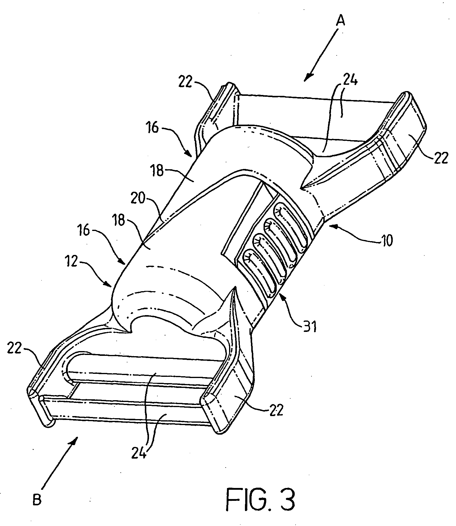
[0022] Referring initially to FIG. 3, the clasp includes two identical parts 10 and 12 that are joined together to form a clasp. As will be described in more detail below, the clasp can be fastened by pushing the two parts 10,12 together in an axial direction indicated by arrows A and B for the two parts 10 and 12. The clasp can be opened by pressing on buttons 31 (only one visible in FIG. 3).

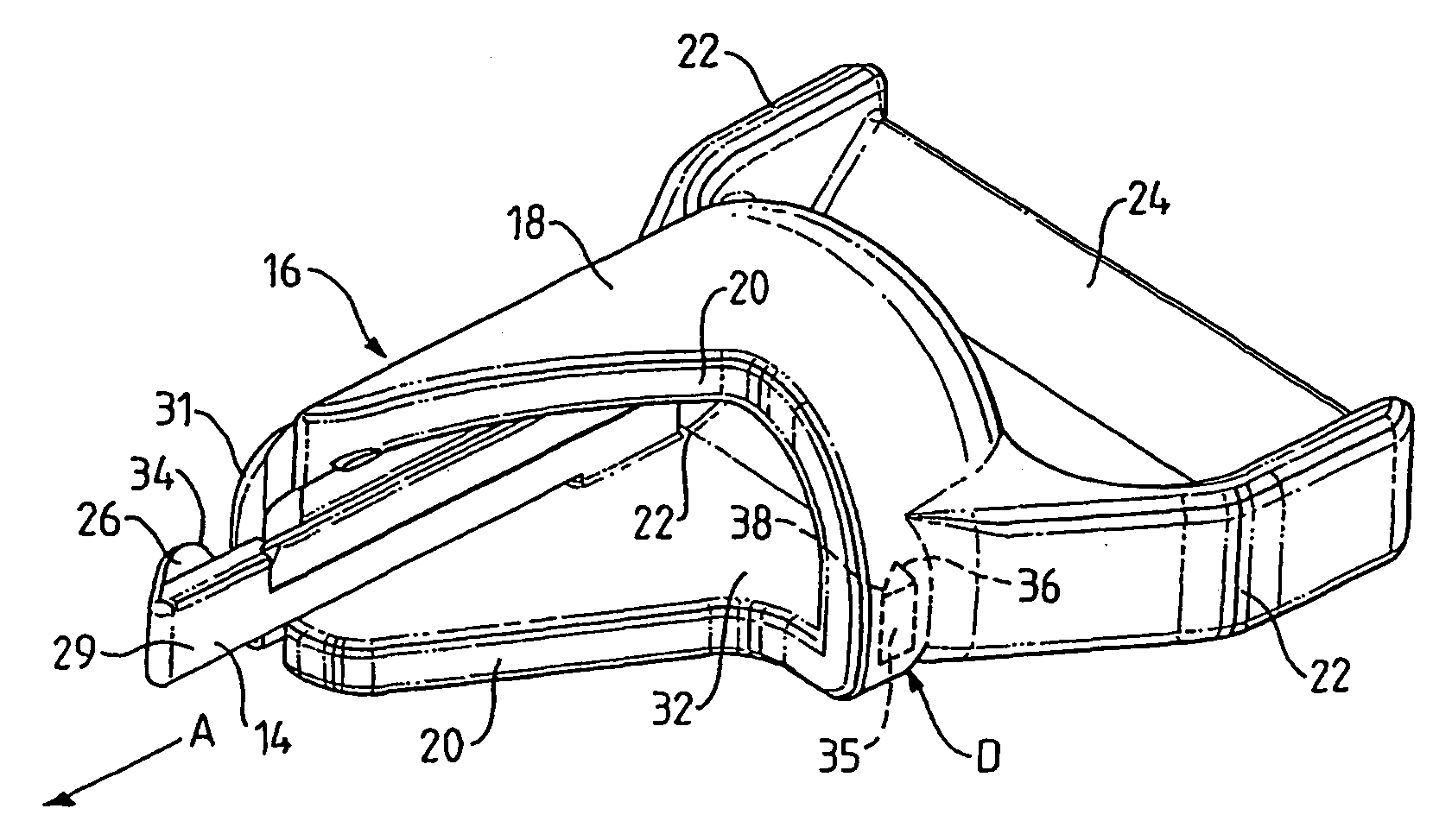
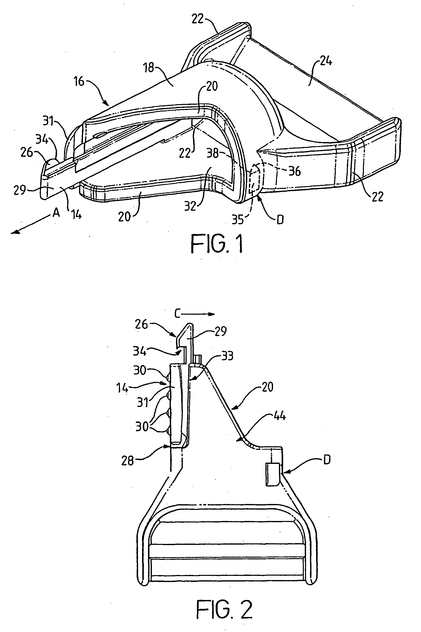
[0023] The two parts 10,12 each have a housing 16 formed by a rounded upper surface 18 and a flat bottom surface (shown in FIGS. 1 and 2). The two parts 10,12 abut each other along a diagonal interface surface 20.

[0024] At the rear of the housing 16, each part has a pair of forked arms 22 and a pair of bars 24 extend between these arms to form a ladder fastening for securing the clasp to webs or straps that are to be joined. The webs are threaded around the bars in a known manner. Alternatively, the webs can be stitched onto the bars 24.

[0025] Referring now to FIGS. 1 and 2, these Figures sh...


PUM


Abstract

A clasp is described that comprises two identical parts (10,12) that can be joined together to fasten the clasp and that can be separated from each other to release the clasp. Each of the first and second parts includes:
  • a) a resilient latch (14) with an outwardly facing barb (26);
  • b) a channel (32) for receiving the barb of the other part;
  • c) a catch (35) located in the channel for engagement with the barb of the other part when the two parts are pushed together in an axial direction (A);
  • d) a housing (16) containing the channel and extending transversely over the width of the part, the housing having an interface surface (20) extending between the latch (14) and the catch (35) and abutting the corresponding interface surface of the other part when the clasp is fastened, the interface surface extending diagonally with respect to the axial direction (A) such that the interface surface in the region of the catch (35) is located axially behind the interface surface in the region of the barb (26);
The barb (26) of each part engages the catch (35) of the other part as the two parts are pushed together, the engagement keeping the parts together. The latches (14) of the two parts can be moved to release each barb (26) from the catch (35) of the other part. The interface surfaces (20) of the two parts are arranged to slide over each other to separate the two parts when the barbs are released from the catches.

Description

TECHNICAL FIELD [0001] The present invention relates to a clasp for joining together two webs. Such devices are sometimes called “clips” and “buckles” and the words “clasp”, “buckles” and “clips” are used synonymously in this specification. BACKGROUND ART [0002] Clasps for connecting together webs and straps are well known and widely used for such diverse applications as securing the two ends of a belt together, closing rucksacks and other bags and sacks, fastening coats and waterproofs and so on. The almost universally accepted design nowadays for such clasp consists of two parts secured to respective webs, one of the parts (the male part) consists of a pair of prongs, each having an outwardly extending barbed tooth and the other part (the female part) has a channel into which the prongs can be pushed. The width of the channel is smaller than the distance between the outsides of the prongs and so, as the male part is pushed into the channel, the prongs are flexed inwardly by the ou...

Claims


Application Information

Patent Timeline
IPC IPC(8): A44B11/25A44B11/26A45C13/10
CPCA44B11/266A44D2200/12A45C13/1084Y10T24/45194Y10S24/38Y10T24/45524Y10S24/42
Inventor SOUTHERN, ANDREW RICHARD
Owner ROYAL COLLEGE OF ART
Why Eureka
Try Eureka