Eureka AIR delivers breakthrough ideas for toughest innovation challenges, trusted by R&D personnel around the world.

System and method for thermal change compensation in an annular isolator

Inactive Publication Date: 2006-05-04
HALLIBURTON ENERGY SERVICES INC
View PDF43 Cites 61 Cited by
  • Summary
  • Abstract
  • Description
  • Claims
  • Application Information

AI Technical Summary

Benefits of technology

[0011] In accordance with another embodiment, the second portion of the sleeve may include a plurality of radialy elastic members disposed between the tubing and the sleeve, to increase the elastic response of the second portion of the sleeve. Thus, the radialy elastic members will be compressed when the tubing is expanded, and the sleeve will be biased to sustain the fluid pressure within the chamber, in response to a change in fluid volume.
[0012] Depending on the specific features implemented, particular embodiments of the present invention may exhibit some, none, or all of the following technical advantages. A technical advantage may be that an expandable sleeve may provide a compliant chamber in which a flowable material may be used to expand the sleeve and form an annular seal with a borehole wall. Another technical advantage may be that the inflatable sleeve may have certain characteristics that allow an annular seal to be formed in an oversized, washed out, and / or irregular shaped borehole. The flexibility of the inflatable sleeve may allow it to conform to such irregular shapes so long as it does not exceed the maximum allowable expansion of the sleeve.
[0013] As still another advantage, the expandable sleeve may include at least one corrugated portion that compensates for volumetric and / or pressure changes caused by temperature changes, to substantially maintain the annular seal, even during variable temperature and / or pressure conditions. Specifically, during high pressure conditions, the corrugated portion may become slightly deformed to account for a greater volume and / or pressure of fluid in the compliant chamber. The corrugated portion may be biased to return to substantially its original shape or to something resembling its original shape, however, when the temperature, pressure and / or volume in the compliant chamber decreases. Accordingly, a further technical advantage may be that the annular seal between the expanded sleeve and the borehole wall may be maintained, even during reduced temperature and / or reduced pressure conditions.

Problems solved by technology

Therefore, any decrease in pressure within the chamber will cause the corrugations to move toward the tubing, thereby tending to reduce the volume of the chamber to compensate for the decrease in pressure.

Method used


Image

  • System and method for thermal change compensation in an annular isolator
  • System and method for thermal change compensation in an annular isolator
  • System and method for thermal change compensation in an annular isolator

Examples


Embodiment Construction

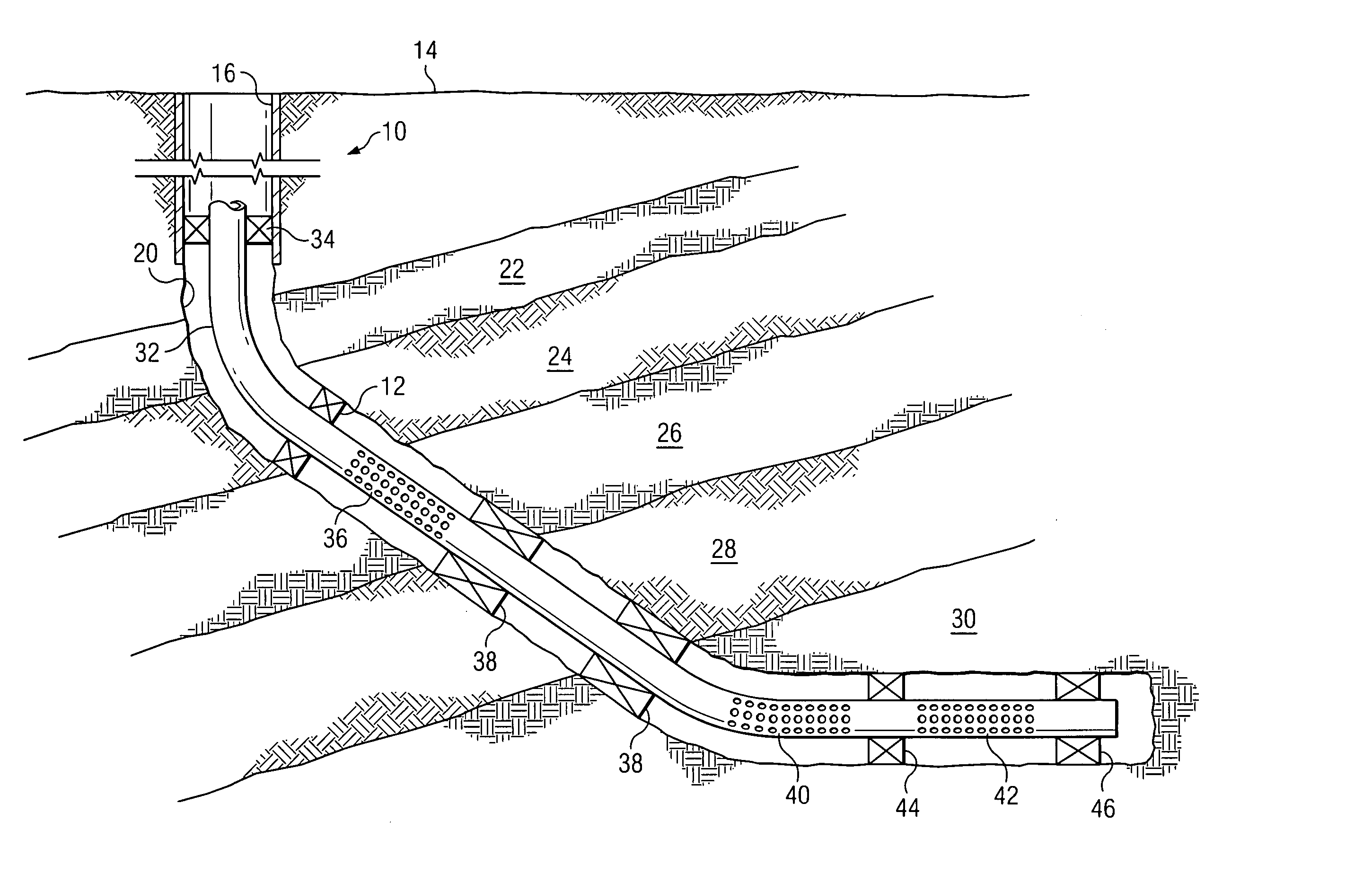
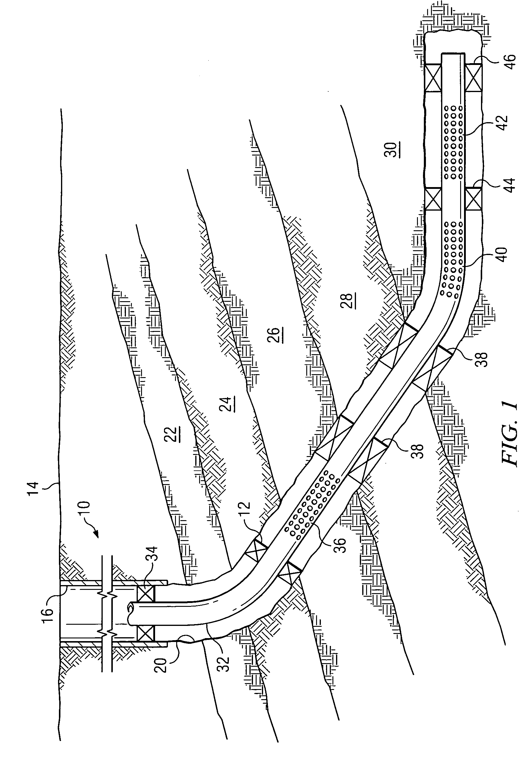
[0023]FIG. 1 is a cross-sectional view of a borehole 10 with an open hole completion and a number of annular isolators 12. For purposes of this document, an “annular isolator” is a material or mechanism or a combination of materials and mechanisms which minimize or prevent the flow of fluids from one side of the isolator to the other, in the annulus between a tubular member in a well and a borehole wall or casing. An annular isolator acts as a pressure bearing seal between two portions of the annulus. Since annular isolators must block flow in the annular space, they may have a ring like or tubular shape having an inner diameter in fluid tight contact with the outer surface of a tubular member and having an outer diameter in fluid tight contact with the wall of a borehole or casing. An annular isolator may extend for a substantial length along a borehole.

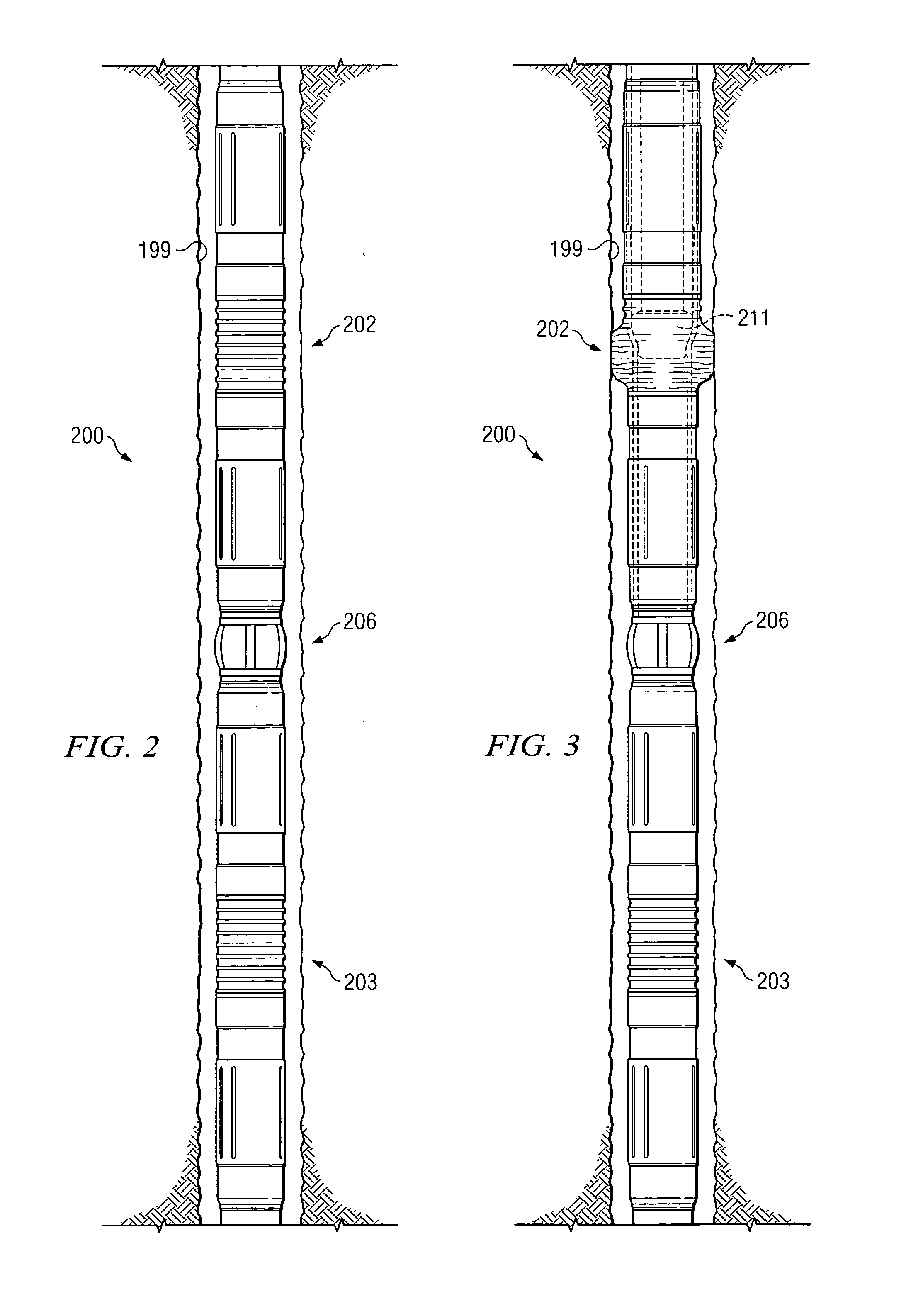
[0024] In accordance with the teachings of the present invention, an annular isolator is provided in which an expandable sleeve i...


PUM


Abstract

In accordance with the teachings of the present invention, a system and method for forming an annular isolator between production tubing and a borehole wall is provided. A section of expandable tubing is installed in a borehole, and a sleeve disposed around a surface of the tubing cooperates with the tubing to form a fluid chamber. The sleeve includes a first portion that is predisposed to expand outwardly under fluid pressure from the fluid chamber, and a second portion that is configured such that, when expanded due to fluid pressure, the second portion stores energy that is biased to sustain the fluid pressure within the chamber, in response to a change in fluid volume. The tubing may be expanded using a tool disposed within the tubing.

Description

TECHNICAL FIELD OF THE INVENTION [0001] The present invention relates in general to borehole annular isolation systems, and more particularly to a system and method for thermal change compensation in an annular isolator. BACKGROUND OF THE INVENTION [0002] Oil and gas wells may pass through a number of zones within a formation to reach the particular oil and / or gas zone(s) of interest. Some of the zones through which the well may pass may be water producing. It is desirable to prevent water from these zones from being produced with the produced oil or gas. Where multiple oil and / or gas zones are penetrated by the same borehole, it is also desirable to isolate the zones to allow separate control of production from each zone for the most efficient production. External packers have been used to provide annular seals or barriers between production tubing and well casing to isolate the various zones. [0003] It has become more common to use open hole completions in oil and gas wells. In th...

Claims


Application Information

Patent Timeline
IPC IPC(8): E21B33/12
CPCE21B33/12E21B33/127E21B43/103
Inventor GANO, JOHN C.ECHOLS, RALPH H.
Owner HALLIBURTON ENERGY SERVICES INC
Why Eureka
Eureka Blog
Learn More