Brake assembly with brake pad position and wear sensor

a technology of wear sensor and brake pad, which is applied in the direction of axially engaging brakes, braking elements, actuators, etc., can solve the problems of inaccurate position information, encoders that consume a large amount of space within the brake assembly, and encoders that provide limited accuracy and dependability

Inactive Publication Date: 2006-05-04
MERITOR HEAVY VEHICLE BRAKING SYST (UK) LTD
View PDF20 Cites 45 Cited by
  • Summary
  • Abstract
  • Description
  • Claims
  • Application Information

AI Technical Summary

Benefits of technology

[0009] Accordingly, the present invention provides an accurate and adaptable method and device fo

Problems solved by technology

Disadvantageously, modifications to specific brake components, such as the operating shaft, may be required to provide mounting and drive features for the encoders.
The mounting and drive features within the brake assembly may wear with use, possibly caus

Method used


Image

  • Brake assembly with brake pad position and wear sensor
  • Brake assembly with brake pad position and wear sensor
  • Brake assembly with brake pad position and wear sensor

Examples


Embodiment Construction

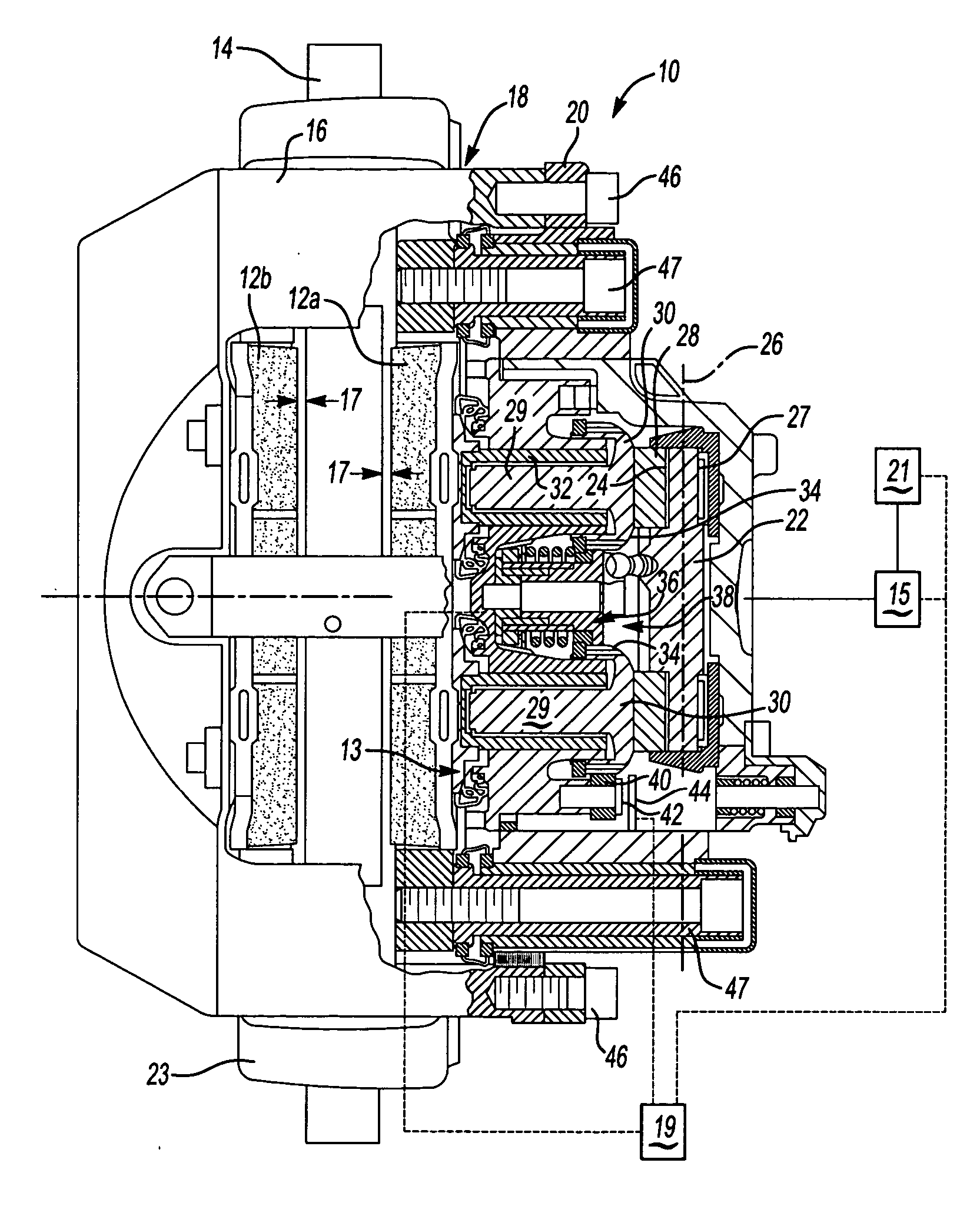
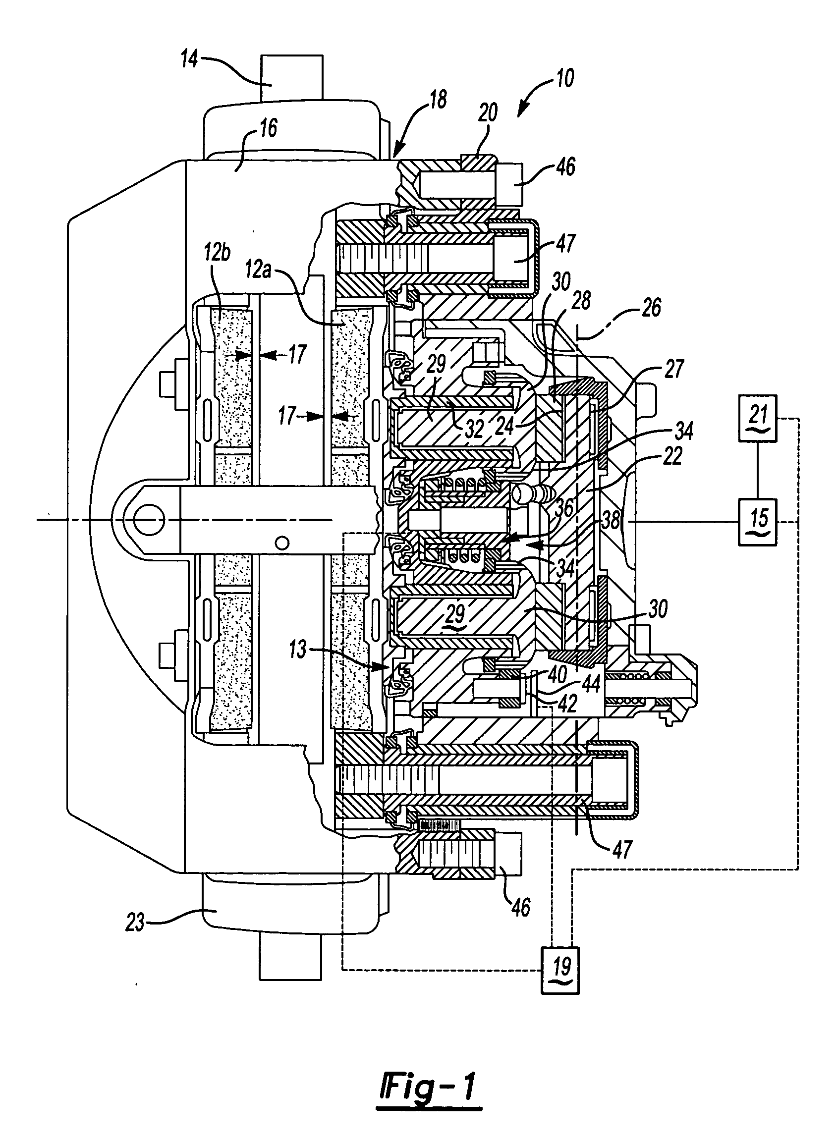
[0016] Referring to FIG. 1, a brake assembly 10 includes a caliper housing 18 including an outer caliper housing 16 bolted to an inner housing 20 by bolts 46. The caliper housing 18 is mounted over a rotor 14 mounted to an axle of a vehicle. The caliper housing 18 slides relative to a fixed caliper pad carrier 23. The caliper housing 18 slides along guide sleeves 47 relative to the fixed caliper pad carrier 23.

[0017] The brake assembly 10 is actuated by movement of an actuator such as an air cylinder and pushrod schematically shown at 15. The actuator 15 may be of any known configuration including, for example, a pneumatically or hydraulically actuated piston or an electric motor. The actuator 15 rotationally drives an operating shaft 22 about an axis 26. A load sensor 21 is provided for detecting a load on the actuator 15.

[0018] The operating shaft 22 is supported on bearings 27 mounted within the inner housing 20 and includes pockets 24 engaged with rollers 28 that are positione...


PUM


Abstract

A brake assembly includes a sensor mounted to a brake component, and which is in communication with a transceiver. The sensor provides position information of the brake component, which is combined with known mechanical relationships between various brake components, to determine a wear state of a brake pad and a clearance between the brake pad and a rotor. The clearance is then adjusted based on signals from the sensor and the known mechanical relationship between the various brake components to maintain the clearance within desired limits.

Description

BACKGROUND OF THE INVENTION [0001] This invention generally relates to a brake assembly, and more specifically to a brake assembly including a sensor for monitoring brake pad wear and clearance between a brake pad and a rotating brake member. [0002] Conventional brake assemblies include an adjustable member known in the art as a tappet assembly driven by a rotatable operating shaft. The operating shaft includes eccentrically positioned pockets that transmit rotational forces through rollers to the tappet assembly. Typically, the tappet assembly includes a threaded nut and screw that are adjusted to change length and thereby a clearance between a brake pad and a rotating brake member such as a rotor. An electric motor is employed to drive either the screw or nut to change the overall length of the tappet assembly and adjust the clearance between the brake pad and the rotor. [0003] The clearance between the brake pad and rotor is monitored by measuring displacement of specific brake c...

Claims


Application Information

Patent Timeline
IPC IPC(8): F16D66/00
CPCF16D55/2255F16D65/183F16D66/02F16D2065/386F16D2121/14
Inventor TAYLOR, MARTINTHOMAS, JEFFREYMORRIS, ROYSTONCLARKE, LESTERNORMAN, MARK
Owner MERITOR HEAVY VEHICLE BRAKING SYST (UK) LTD
Why Eureka
Try Eureka