Driving apparatus

a technology of driving apparatus and transmission shaft, which is applied in the direction of friction gearings, dynamo-electric machines, and grinding gearings, etc., can solve the problems of low transmission torque towards the shaft, low safety, and abrasion of the tooth plane, and achieve the effect of preventing interferen

Inactive Publication Date: 2006-05-04
MARUYASU KIKAI KK
View PDF4 Cites 32 Cited by
  • Summary
  • Abstract
  • Description
  • Claims
  • Application Information

AI Technical Summary

Benefits of technology

[0029] Since the non-magnetized region is formed in a partitioned area between N-pole and S-pole alternately arranged in spiral manner on the truncated conical shaped magnetic wheel, it is possible to prevent a simultaneous occurrence of absorption and repelling with respect to the magnetic wheel as a counterpart. Accordingly, it is possible to prevent interference (force which cancels rotation) from arising on the magnetic wheel.

Problems solved by technology

However, since this conventional transmission driving device using gears transmits the rotational force by allowing the gears to be engaged with one another, there is a possibility of tooth plane abrasion, dust generation, and noise occurrence, and further, a high torque or impact may cause a risk of damage.
Therefore, transmission torque towards a shaft (for example, roller shaft) is limited and low, on which the follower magnetic wheel being ultimately rotated is installed.
Therefore, this kind of driving apparatus has been used for conveying relatively lightweight items or the like, and it has been inadequate to heavy load conveyance.
However, if the diameters of the drive magnetic wheel and the follower magnetic wheel are made larger, it is a matter of course that cost is increased, and the entire driving apparatus grows in size.
Consequently, it causes a problem that a system which utilizes this driving apparatus also grows in size.

Method used


Image

  • Driving apparatus
  • Driving apparatus
  • Driving apparatus

Examples


example 1

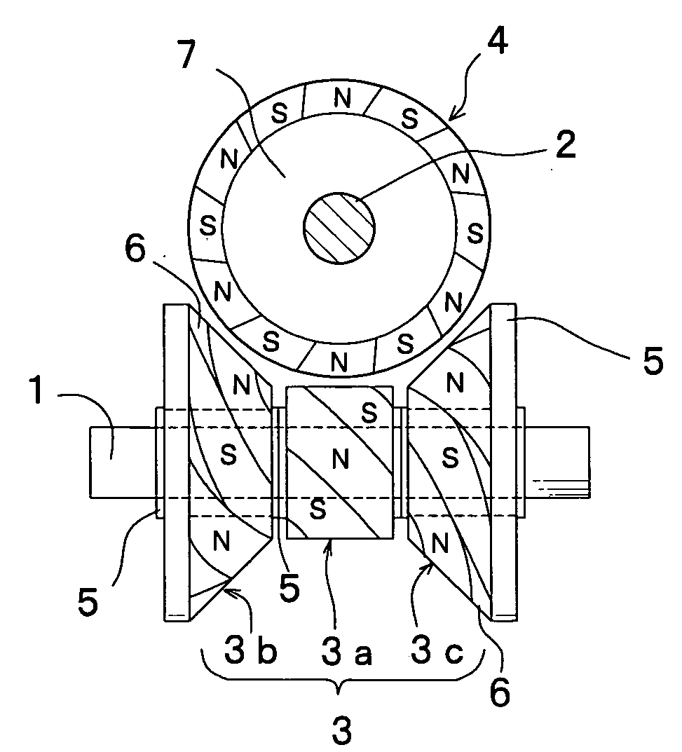
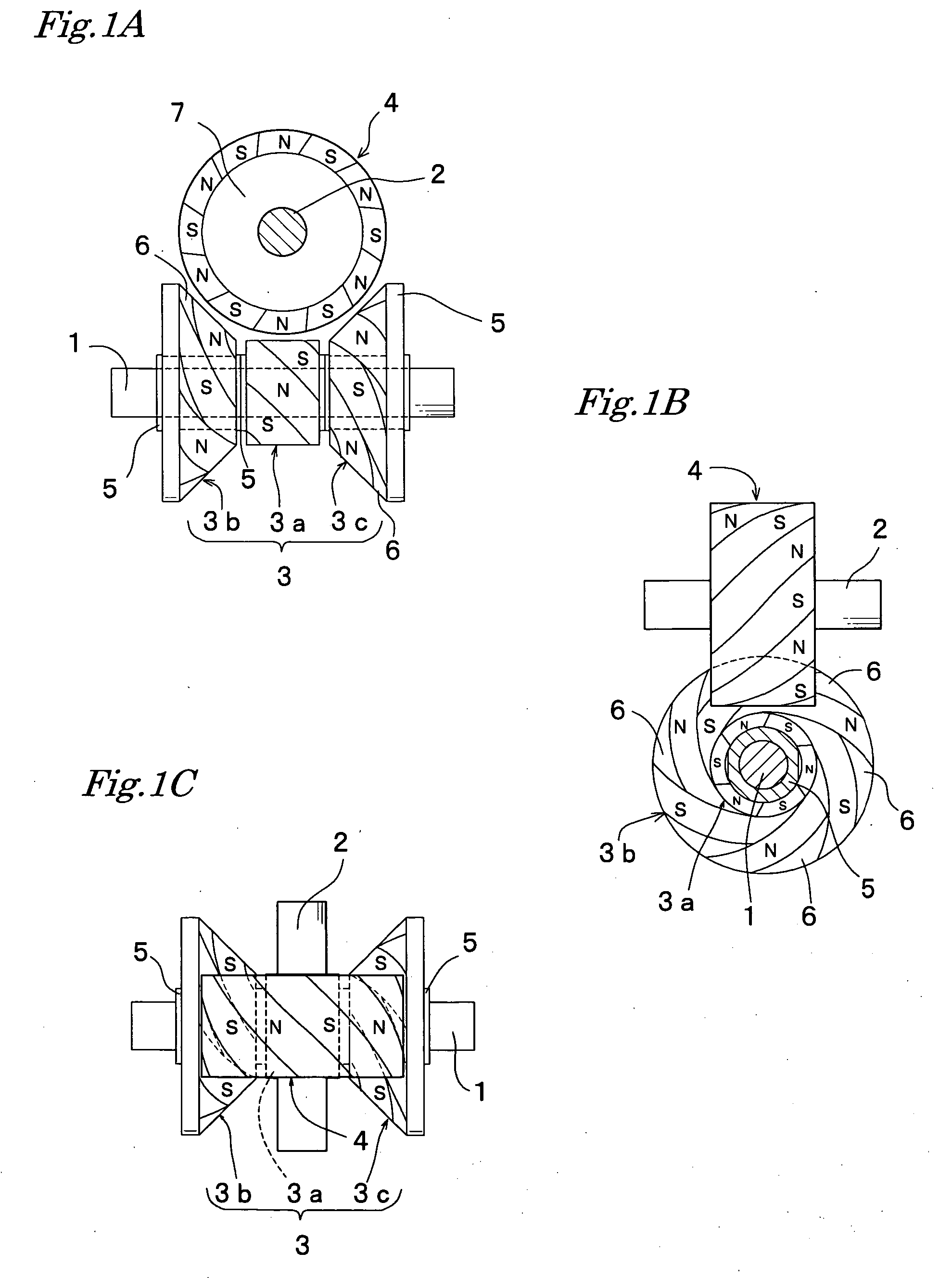
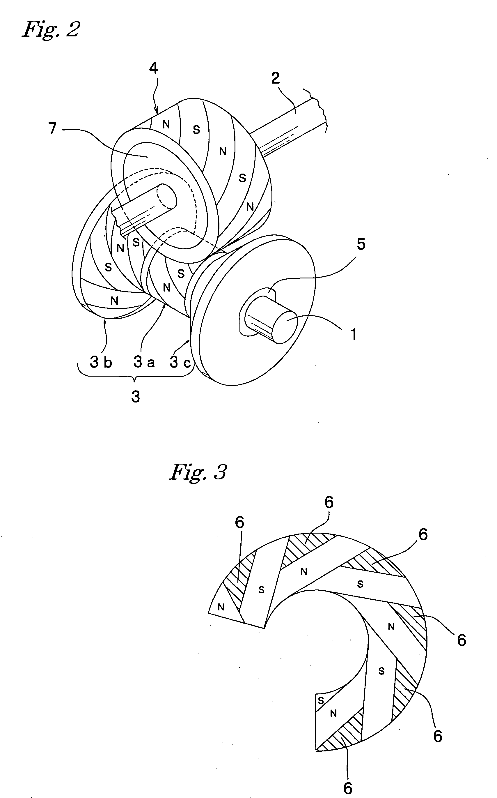
[0040]FIG. 1 and FIG. 2 show a driving apparatus in which a magnetic action is produced on three points respectively at three places on the drive magnetic wheel installed on the drive shaft with respect to the follower cylindrical shaped magnetic wheel installed on the follower shaft, both magnetic wheel being arranged in a non-contact state, and then power is transmitted. In those figures, reference numeral 1 indicates a drive shaft, numeral 2 indicates a follower shaft, both being arranged in such a manner as crossing each other at right angles, numeral 3 indicates a drive magnetic wheel fitted into the drive shaft 1 and fixed thereon, and numeral 4 indicates a follower magnetic wheel fitted into the follower shaft 2 and fixed thereon.

[0041] The drive magnetic wheel 3 fitted into the drive shaft 1 and fixed thereon includes a cylindrical shaped magnetic wheel 3a and truncated conical shaped magnetic wheels 3b and 3c placed on both sides in the axial direction of the cylindrical s...

example 2

[0050]FIG. 4 and FIG. 5 show a driving apparatus having a drive magnetic wheel 8 fixed on the drive shaft 1 and a follower magnetic wheel 9 fixed on the follower shaft 2, both formed in an hourglass shape, and those magnetic wheels 8 and 9 are arranged in such a manner that concave curves thereof cross each other at right angles in a non-contact state.

[0051] Similarly to the follower magnetic wheel 4 as described in the Example 1 above, the hourglass shaped magnetic wheel 8 includes a cylindrical shaped magnetic wheel 8a, and truncated conical shaped magnetic wheels 8b, 8c on both sides in the axial direction of the magnetic wheel 8a, the truncated surfaces being arranged to be opposed to each other. In a similar manner, the hourglass shaped magnetic wheel 9 includes a cylindrical shaped magnetic wheel 9a, and truncated conical shaped magnetic wheels 9b, 9c on both sides in the axial direction of the magnetic wheel 9a, the truncated surfaces being arranged to be opposed to each oth...

example 3

[0055]FIG. 6 and FIG. 7 show a driving apparatus having a drive magnetic wheel 10 fixed on the drive shaft 1 and a follower magnetic wheel 11 fixed on the follower shaft 2, both formed in an hourglass shaped, and those magnetic wheels 10 and 11 are arranged on the axes in such a manner that the truncated surfaces of the truncated conical shaped magnetic wheels are opposed to each other, and concave curves of the drive magnetic wheel 10 and the follower magnetic wheel 11 cross each other at right angles in a non-contact state.

[0056] In other words, the configuration in Example 3 corresponds to that of the drive magnetic wheel 8 and the follower magnetic wheel 9 shown in Example 2 from which the cylindrical shaped magnetic wheels 8a and 9a are removed. Here, the truncated conical shaped magnetic wheels 10a, 10b, and 11a, 11b respectively constituent elements of the drive magnetic wheel 10 and the follower magnetic wheel 11, are formed so that each has the same diameter.

[0057] In add...


PUM


Abstract

The present invention provides a driving apparatus utilizing magnetic force, which is capable of establishing an enhanced level of higher torque, without enlarging the diameters of the drive magnetic wheel and the follower magnetic wheel, or without installing another transmission system branching off the drive shaft. The driving apparatus where the drive shaft and the follower shaft are arranged in such a manner as crossing each other at right angles, and a non-contact type power transmission mechanism utilizing magnetic force performs power transmission from the drive shaft to the follower shaft, wherein, magnetic wheels are installed respectively on the drive shaft and the follower shaft, each of the magnetic wheels being formed by spirally magnetized into N-pole and S-pole alternately, and plural points are coaxially provided which produce magnetic actions from one magnetic wheel to another magnetic wheel.

Description

BACKGROUND OF THE INVENTION [0001] 1. Field of the Invention [0002] The present invention relates to a driving apparatus which utilizes a magnetic wheel so as to transmit rotational driving force without any contact action. [0003] 2. Description of the Related Art [0004] Generally, a transmission driving device using gears is employed as a means for transmitting a rotational force in a machine tool, industrial machine, and the like. However, since this conventional transmission driving device using gears transmits the rotational force by allowing the gears to be engaged with one another, there is a possibility of tooth plane abrasion, dust generation, and noise occurrence, and further, a high torque or impact may cause a risk of damage. [0005] Considering the above situation, in order to solve the problems of the conventional driving device using gears as described above, there is proposed a driving apparatus utilizing a magnetic wheel which transmits a rotational force in a non-con...

Claims


Application Information

Patent Timeline
Patent Type & Authority Applications(United States)
IPC IPC(8): H02K7/10
CPCH02K49/102F16H13/12
Inventor YODA, KAZUEMIYASAKA, TETSUO
Owner MARUYASU KIKAI KK
Why Eureka
Try Eureka