Methods and apparatus for precision control of print head assemblies

a technology of precision control and print head, applied in the field of printing, can solve the problems of difficulty in accurately and precisely displaying inkjet ink or other materials on a substrate, and achieve the effect of improving the accuracy and precision of printing head assembly

Inactive Publication Date: 2006-05-04
APPLIED MATERIALS INC
View PDF99 Cites 17 Cited by
  • Summary
  • Abstract
  • Description
  • Claims
  • Application Information

AI Technical Summary

Problems solved by technology

One problem with effective employment of inkjet printing is that it is difficult to inkjet ink or other material accurately and precisely on a substrate while having high throughput.

Method used


Image

  • Methods and apparatus for precision control of print head assemblies
  • Methods and apparatus for precision control of print head assemblies
  • Methods and apparatus for precision control of print head assemblies

Examples


Embodiment Construction

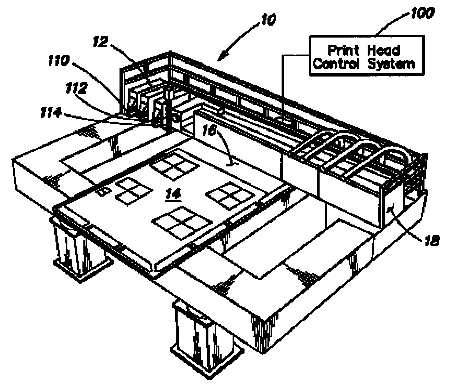
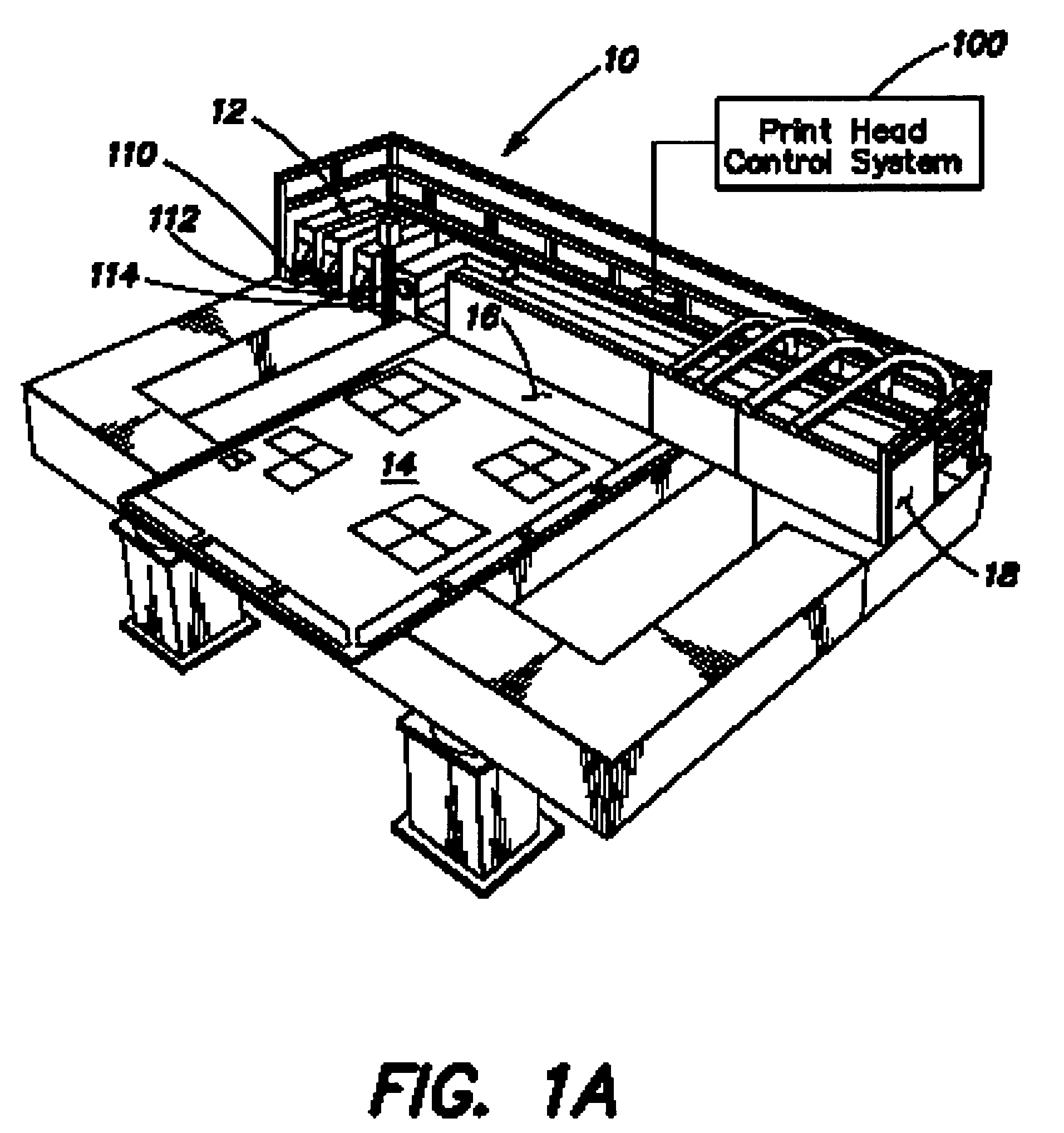
[0016] Inkjet printers frequently make use of one or more inkjet print heads (or heads) mounted within a carriage that is moved back and forth across a substrate, such as glass for a flat panel display. In some printers, the substrate is additionally or alternatively moved relative to the heads on a moving table top called a stage. As the substrate travels relative to the heads, a control system activates individual nozzles within the heads to deposit or eject ink (or other fluid) droplets onto the substrate to form images. The images to be printed are represented as electronic images stored in a memory of the control system. In other words, pixels of an electronic image are used to represent drop locations on the substrate.

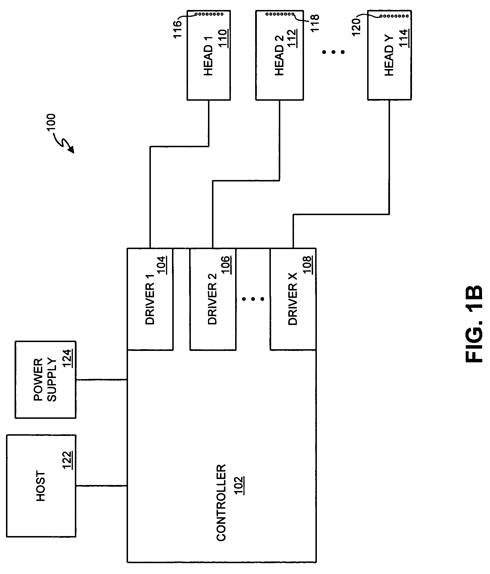
[0017] Activating a nozzle may include sending a fire pulse signal or pulse voltage to the individual nozzle to cause an ejection mechanism to dispense a quantity of ink. In some heads, the pulse voltage is used to trigger, for example, a piezoelectric element t...


PUM


Abstract

The present invention provides methods and apparatus for controlling the quantity of fluid output (e.g., drop size) by individual nozzles of a print head to a very high precision at a frequency equal to the frequency at which fluid is normally dispensed. This is achieved by mapping fluid quantity control information into the data that represents the image to be printed. Data representative of an image is received and converted into pixel data. In at least one embodiment, the pixel data includes pixels represented by N bits, and the N bits may represent a drop size for the pixel and a union of the N bits may represent a nozzle status. A print head may be controlled based on the pixel data, and the print head may include nozzles that are each adapted to deposit at least one drop size quantity of a fluid on a substrate.

Description

CROSS REFERENCE TO RELATED APPLICATIONS [0001] The present application is related to the following commonly-assigned, co-pending U.S. patent application, which is hereby incorporated herein by reference in its entirety for all purposes: [0002] U.S. Provisional Patent Application Ser. No. 60 / 625,550, filed Nov. 4, 2004 and entitled “APPARATUS AND METHODS FOR FORMING COLOR FILTERS IN A FLAT PANEL DISPLAY BY USING INKJETTING.”FIELD OF THE INVENTION [0003] The present invention relates generally to systems for printing, and is more particularly concerned with precision control of print head assemblies. BACKGROUND OF THE INVENTION [0004] The flat panel display industry has been attempting to employ inkjet printing to manufacture display devices, in particular, color filters. One problem with effective employment of inkjet printing is that it is difficult to inkjet ink or other material accurately and precisely on a substrate while having high throughput. Accordingly, there is a need for ...

Claims


Application Information

Patent Timeline
Patent Type & Authority Applications(United States)
IPC IPC(8): B41J29/38
CPCB41J2/04541B41J2/0456B41J2/04581B41J2/04591B41J2/04593B41J2/2128B41J2202/09G02F1/133516H04N1/4015
Inventor SHAMOUN, BASSAMJOZWIAK, JANUSZSHANG, QUANYUANJI, HONGBIN
Owner APPLIED MATERIALS INC
Why Eureka
Try Eureka