Light emitting diode and backlight apparatus having the same

Inactive Publication Date: 2006-05-04
SAMSUNG ELECTRO MECHANICS CO LTD
View PDF2 Cites 30 Cited by
  • Summary
  • Abstract
  • Description
  • Claims
  • Application Information

AI Technical Summary

Benefits of technology

[0014] The present invention has been made to solve the foregoing problems of the prior art and it is therefore an object of the present invention to provide an LED and an LCD backlight apparatus having the same, in which a lower side wall is projected from the LED between and beyond LED terminal

Problems solved by technology

This as a result creates a dark area 34 to exist in a portion of the reflective sheet 16 where light L is faint, thereby lowering the efficiency of the entire LCD backlight apparatus.
Furthermore, according to the miniaturization of a mobile communication device,

Method used


Image

  • Light emitting diode and backlight apparatus having the same
  • Light emitting diode and backlight apparatus having the same
  • Light emitting diode and backlight apparatus having the same

Examples


Example

[0035] The following detailed description will present preferred embodiments of the present invention with reference to the accompanying drawings.

[0036] First a preferred embodiment of an LED according to the invention will be described with reference to FIGS. 6 to 8, in which FIG. 6 is a front elevation view illustrating a preferred embodiment of an LED according to the invention, FIG. 7 is a side elevation view of the LED shown in FIG. 6, and FIG. 8 is a vertical cross-sectional view of the LED shown in FIG. 6.

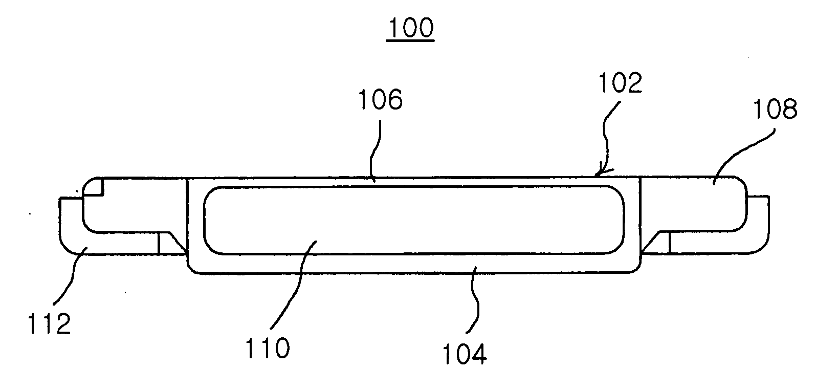
[0037] As shown in FIGS. 6 to 8, an LED 100 includes an LED chip 120, a package body or LED body 102 having a cup-shaped cavity 110, which houses the LED chip 120 therein, and a pair of terminals 112 attached to projections 108 at opposite lateral portions of the LED body 102 to electrically connect the LED chip 120 with an external power source.

[0038] The cup-shaped cavity 110 is opened upward from the plane of FIG. 6 forming an LED window to introduce light from the LED...


PUM


Abstract

An LED and an LCD backlight apparatus having the same. In the LED, a lower side wall projected from the LED between and beyond LED terminals, such that the bottom of an LED window in the vicinity of the lower side wall is positioned flush with or under the terminals, and a recess is formed in a board of the backlight apparatus to receive the lower side wall. The height of the LED mounted on the backlight apparatus can be reduced and light efficiency can be improved.

Description

RELATED APPLICATION [0001] The present application is based on and claims priority from Korean Application Number 10-2004-0088364, filed Nov. 2, 2004, the disclosure of which is hereby incorporated by reference herein in its entirety. BACKGROUND OF THE INVENTION [0002] 1. Field of the Invention [0003] The present invention relates to a Light Emitting Diode (LED) and a backlight apparatus having the same, and more particularly, in which a side wall of the LED is projected between and beyond terminals thereof and a recess for receiving the side wall is formed in a board of the backlight apparatus in order to improve light efficiency as well as reduce the height of the LED mounted on the backlight apparatus. [0004] 2. Description of the Related Art [0005] A Liquid Crystal Display (LCD) backlight apparatus of a mobile communication device has a general structure as shown in FIG. 1. That is, the backlight apparatus 10 has a planar light guide plate 14 placed on a board 12 and an array of...

Claims


Application Information

Patent Timeline
IPC IPC(8): F21V7/04G02F1/13357F21V8/00G02B6/00H01L33/56H01L33/60
CPCG02B6/0031G02B6/0073G02B6/009G02F1/1335
Inventor KIM, CHANG WOOKSOUNG, YOUNG JAE
Owner SAMSUNG ELECTRO MECHANICS CO LTD
Why Eureka
Try Eureka