Image forming method, and image forming apparatus and process cartridge using the image forming method

a technology of image forming and process cartridge, which is applied in the field of image forming method, can solve the problems of deterioration of image quality, serious reduction of surface resistivity of photosensitive layer, and relatively low mechanical and chemical durability of organic photoreceptors, and achieve good abrasion resistance and scratch resistance

Inactive Publication Date: 2006-05-04
RICOH KK
View PDF11 Cites 44 Cited by
  • Summary
  • Abstract
  • Description
  • Claims
  • Application Information

AI Technical Summary

Benefits of technology

[0037] In the image forming method of the present invention, a photoreceptor having a crosslinked charge transport layer as an outermost layer is used. The crosslinked charge transport layer is prepared by crosslinking a radical polymerizable polyfunctional monomer having three or more radical polymerizable functional groups and having no charge transport structure and a radical polymerizable functional monomer having one or more radical polymerizable functional groups and a charge transport structure. This photoreceptor has good abrasion resistance and good scratch resistance, but the surface of the photoreceptor is very slightly abraded when image forming operations are repeatedly performed thereon. Therefore, charging products generated in charging processes are not accumulated on the surface of the photoreceptor because the charging products present on the surface of the photoreceptor are removed as the surface is slightly abraded (i.e., the surface is always renewed).
[0038] In addition, a cleaning device configured to attract toner particles utilizing an electrostatic force is used for the image forming method instead of a cleaning blade or a combination of a cleaning blade and an assistant cleaning member configured to attract toner particles utilizing an electrostatic force is used, an excessive stress is not applied to the photoreceptor. Further, a polishing member configured to actively polish the surface of the photoreceptor to an extent such that image qualities are not deteriorated is used. Therefore, high quality images can be stably produced for a long period time.
[0039] It is preferable that a voltage is applied between a cleaning member of the cleaning device and the photoreceptor such that the cleaning member electrostatically attracts residual toner particles present on the surface of the photoreceptor. By using this cleaning method, residual toner particles can be well removed even when the toner is a spherical toner having a small particle diameter. Therefore, occurrence of the problem in that the image qualities are deteriorated due to residual toner particles can be prevented.
[0040] The toner used for the image forming method of the present invention preferably has a volume average particle diameter (Dv) of from 3 to 9 μm, a ratio (Dv / Dn) of the volume average particle diameter (Dv) to the number average particle diameter (Dn) of from 1.01 to 1.25, and an average circularity of not less than 0.950 and less than 1.0. By using such a toner, high definition images can be produced. In addition, by using a urea-modified polyester resin as a binder resin of the toner having such a sharp particle diameter distribution as mentioned above, the toner has a good combination of fluidity, low temperature fixability and hot offset resistance, and can produce color images having a good combination of transparency and glossiness.

Problems solved by technology

However, the organic photoreceptors have relatively low mechanical and chemical durability compared to inorganic photoreceptors.
In addition, a part of the charging products invades into the photosensitive layer, and thereby the electrostatic properties of the photoreceptor are deteriorated, resulting in deterioration of image qualities.
In particular, when the charging products or the reaction products of the charging products and the materials constituting the photosensitive layer absorb the moisture in the air under high humidity conditions, the surface resistivity of the photosensitive layer seriously decreases, and thereby abnormal images such as tailed images and blurred images are produced.
Such abnormal images are fatal defects for high definition full color images.
In addition, published unexamined Japanese patent applications Nos.
The chemical durability of a photoreceptor is typically deteriorated by corona charging performed in a charging process and a transferring process.
Namely, even when these methods are used, it is hard for a photoreceptor to be stably used for a long period of time.
In a tandem type high speed color printer in which a full color image is formed by forming four color images on respective photoreceptors, transferring the four color images onto an intermediate transfer medium one by one, and then transferring the four color images to a receiving material at the same time, a problem in that the resultant full color image has poor color balance tends to occur because the abrasion losses of the four photoreceptors are different and therefore the photosensitivities of the photoreceptors are different from each other.
In addition, even when only one color image is blurred, the image quality of the resultant full color image seriously deteriorates.
Further, when a photoreceptor is repeatedly used for a long period of time at a high speed, the abrasion loss of the photoreceptor seriously increases, and therefore the photoreceptor has to be frequently replaced with new one.
However, such spherical toners prepared by a polymerization method have several drawbacks.
Among the drawbacks, the most serious drawback is that toner particles remaining on the surface of a photoreceptor even after a cleaning process cannot be perfectly removed therefrom, resulting in occurrence of a cleaning problem for the photoreceptor.
In addition, the tip of a cleaning blade is not smoothly contacted with the surface of a photoreceptor when images are formed at a high speed, thereby causing a problem in that the tip of the cleaning blade is turned around and the following toner particles cannot be removed by the deformed portion of the cleaning blade particularly when the toner particles have a small particle diameter.
However, in these cleaning methods, residual toner particles are scraped off by a cleaning blade and thereby a wax included in a surface portion of the toner particles is exuded therefrom due to the pressure of the cleaning blade if the toner includes a polyester resin having a low melt viscosity and a sharp melting property.
This wax film deteriorates the image qualities.
Namely, when the friction coefficient of the photoreceptor is decreased due to formation of the wax film, the adhesion of toner particles to the photoreceptor decreases, and thereby the toner particles constituting a toner image tend to be abnormally transferred from the photoreceptor to a receiving material, resulting in formation of a scattered toner image.
In addition, when a photoreceptor is repeatedly charged, the surface of the photoreceptor is deteriorated.
However, such a technique produces some side effects.

Method used


Image

  • Image forming method, and image forming apparatus and process cartridge using the image forming method
  • Image forming method, and image forming apparatus and process cartridge using the image forming method
  • Image forming method, and image forming apparatus and process cartridge using the image forming method

Examples


first embodiment

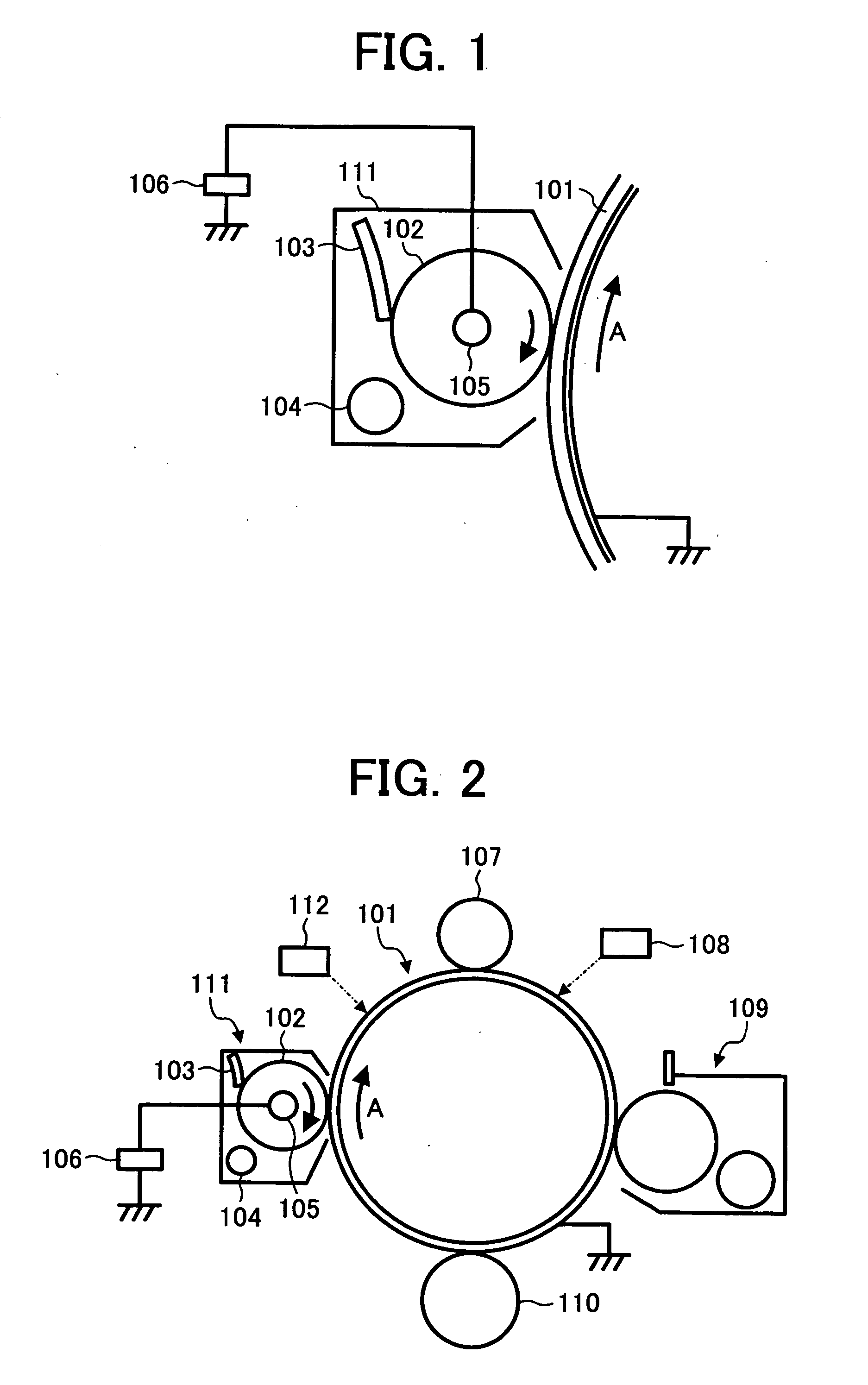
[0441]FIG. 1 is a schematic view illustrating a cleaning device for use in the image forming apparatus of the present invention.

[0442] The photoreceptor prepared above is used as an image bearing member 101. As illustrated in FIG. 1, a cleaning device 111 includes a cleaning member 102, a scraper blade 103 and a feeding coil 104. The cleaning member 102 includes a metal shaft 105, and an electroconductive elastic layer which is formed on the metal shaft 105 and which is made of, for example, a molded electroconductive rubber layer and has a rubber hardness of from 15 to 80° and a volume resistivity of from 105 to 1015 Ω·cm. In addition, a tube or a layer which is made of an electroconductive fluorine-containing resin having a volume resistivity of from 106 to 1016 Ω·cm can be overlaid on the elastic layer.

[0443] The cleaning member 102 is pressed toward the surface of the image bearing member 101 by a pressing member (not shown) at a pressure of from 300 to 700 gf. In addition, th...

second embodiment

[0487]FIG. 6 is a schematic view illustrating another embodiment of the cleaning device for use in the image forming apparatus of the present invention. The photoreceptor (1) is used as the image bearing member 601.

[0488] Toner particles 615 remaining on an image bearing member 601 are clockwise fed and are removed from the surface of the image bearing member by a brush roller 616. Toner particles adhered to the brush roller and remaining thereon without being removed from the brush roller are knocked-off by a bias roller 617. In this case, the bias roller may be rotated or fixed. The toner particles released from the brush roller 616 or the bias roller 617 are collected by a collection roller 619 provided in a cleaning unit 618 to be fed to a developing tank and to be reused. Alternatively, in order to stabilize the image forming system, the collected toner particles may be fed to a waste toner bottle to be disposed of.

[0489] When the residual toner particles have a charge, a bia...

third embodiment

[0492] In the toner image transfer process, by applying a high voltage, a toner image on the image bearing member is electrostatically transferred to a receiving material or an intermediate transfer medium which is typically used for forming a full color image. In this case, a discharging phenomenon may be caused between the image bearing member and the electrode applying the transfer bias, thereby causing a problem in that the polarity of toner particles having a small amount of charge or toner particles having an abnormal charge is reversed. Therefore, a problem in that the residual toner includes toner particles with a negative charge and toner particles with a positive charge occurs. The toner particles in this state are illustrated in FIG. 27.

[0493] In order to avoid such a problem (i.e., in order to uniformize the polarity of the residual toner), charging is performed before the cleaning process. Since a high voltage is directly applied to the image bearing member in this cha...


PUM

PropertyMeasurementUnit
thicknessaaaaaaaaaa
volume average particle diameteraaaaaaaaaa
thicknessaaaaaaaaaa

Abstract

An image forming method including forming a toner image on an image bearing member; transferring the toner image onto a receiving material; and then cleaning the surface of the image bearing member with a cleaning member while applying a voltage to the cleaning member such that the cleaning member electrostatically attracts toner particles remaining on the image bearing member, wherein the image bearing member has, as an outermost layer, a crosslinked charge transport layer comprising a crosslinked resin including at least one unit obtained from at least one radical polymerizable polyfunctional monomer having three or more radical polymerizable functional groups and no charge transport structure, and a unit obtained from a radical polymerizable functional monomer having one or more radical polymerizable functional groups and a charge transport structure. An image forming apparatus and a process cartridge using the image forming method are also provided.

Description

BACKGROUND OF THE INVENTION [0001] 1. Field of the Invention [0002] The present invention relates to an image forming method, and more particularly to an electrophotographic image forming method. In addition, the present invention also relates to an image forming apparatus and a process cartridge using the image forming method. [0003] 2. Discussion of the Background [0004] Electrophotography is widely used for image forming apparatuses such as copiers and laser printers. Electrophotographic image forming methods typically include the following processes: [0005] (1) charging an electrophotographic photoreceptor (herein after referred to as a photoreceptor) serving as an image bearing member (charging process); [0006] (2) irradiating the charged photoreceptor with imagewise light to form an electrostatic latent image on the surface of the photoreceptor (light irradiating process); [0007] (3) developing the electrostatic latent image with a developer including a toner to form a toner i...

Claims


Application Information

Patent Timeline
Patent Type & Authority Applications(United States)
IPC IPC(8): G03G21/10
CPCG03G5/0542G03G5/0546G03G5/0592G03G5/1473G03G5/14734G03G5/14791G03G9/0819G03G9/0821G03G9/0827G03G9/08755G03G9/08764G03G9/08791G03G9/08793G03G2221/0005G03G21/0035G03G21/0076
Inventor OHSHIMA, KOHICHISUZUKI, YASUOSUZUKI, TETSUROSASAKI, MICHITAKA
Owner RICOH KK
Why Eureka
Try Eureka